Page 2935 of 4770
F00116
Right Front
Speed Sensor
Left Front
Speed Sensor
Right Rear
Speed Sensor
Left Rear
Speed Sensor2
1A18
A19 12
1
2
2 1A18
A18
A18
A19
A19
A19ABS ECU
W
B
R
G
B
G RB WG R
IK2
IL1
ID1IK2
ID1 IL11
6
2
1
3
983
FR+
FR±
FL+
FL±
RR+
RR±
RL+
RL±Right Front
Speed Sensor
Left Front
Speed Sensor
Left Rear
Speed Sensor2
1A18
A19 12
1
2
2 1A18
A18
A18
A19
A19
A19ABS ECU
W
B
R
G
W
G RB WG R
IK2
IL1
ID1IK2
ID1 IL11
6
2
1
3
99
93
FR+
FR±
FL+
FL±
RR+
RR±
RL+
RL± 2
10
23
R
G22
± DIAGNOSTICSANTI±LOCK BRAKE SYSTEM (DENSO Made)
DI±515
750 Author�: Date�:
WIRING DIAGRAM
Page 2936 of 4770
R14205
1
2
R14213
12 12
12
12
12
1212
DI±516
± DIAGNOSTICSANTI±LOCK BRAKE SYSTEM (DENSO Made)
751 Author�: Date�:
INSPECTION PROCEDURE
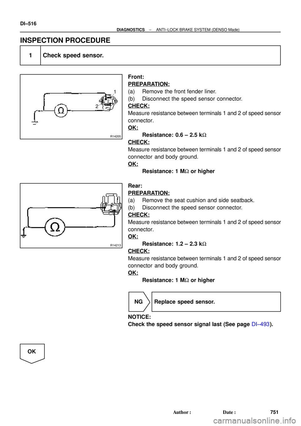
1 Check speed sensor.
Front:
PREPARATION:
(a) Remove the front fender liner.
(b) Disconnect the speed sensor connector.
CHECK:
Measure resistance between terminals 1 and 2 of speed sensor
connector.
OK:
Resistance: 0.6 ± 2.5 kW
CHECK:
Measure resistance between terminals 1 and 2 of speed sensor
connector and body ground.
OK:
Resistance: 1 MW or higher
Rear:
PREPARATION:
(a) Remove the seat cushion and side seatback.
(b) Disconnect the speed sensor connector.
CHECK:
Measure resistance between terminals 1 and 2 of speed sensor
connector.
OK:
Resistance: 1.2 ± 2.3 kW
CHECK:
Measure resistance between terminals 1 and 2 of speed sensor
connector and body ground.
OK:
Resistance: 1 MW or higher
NG Replace speed sensor.
NOTICE:
Check the speed sensor signal last (See page DI±493).
OK
Page 2937 of 4770
BR3795
OK NG OK NG
OK NGOK NG
W04200
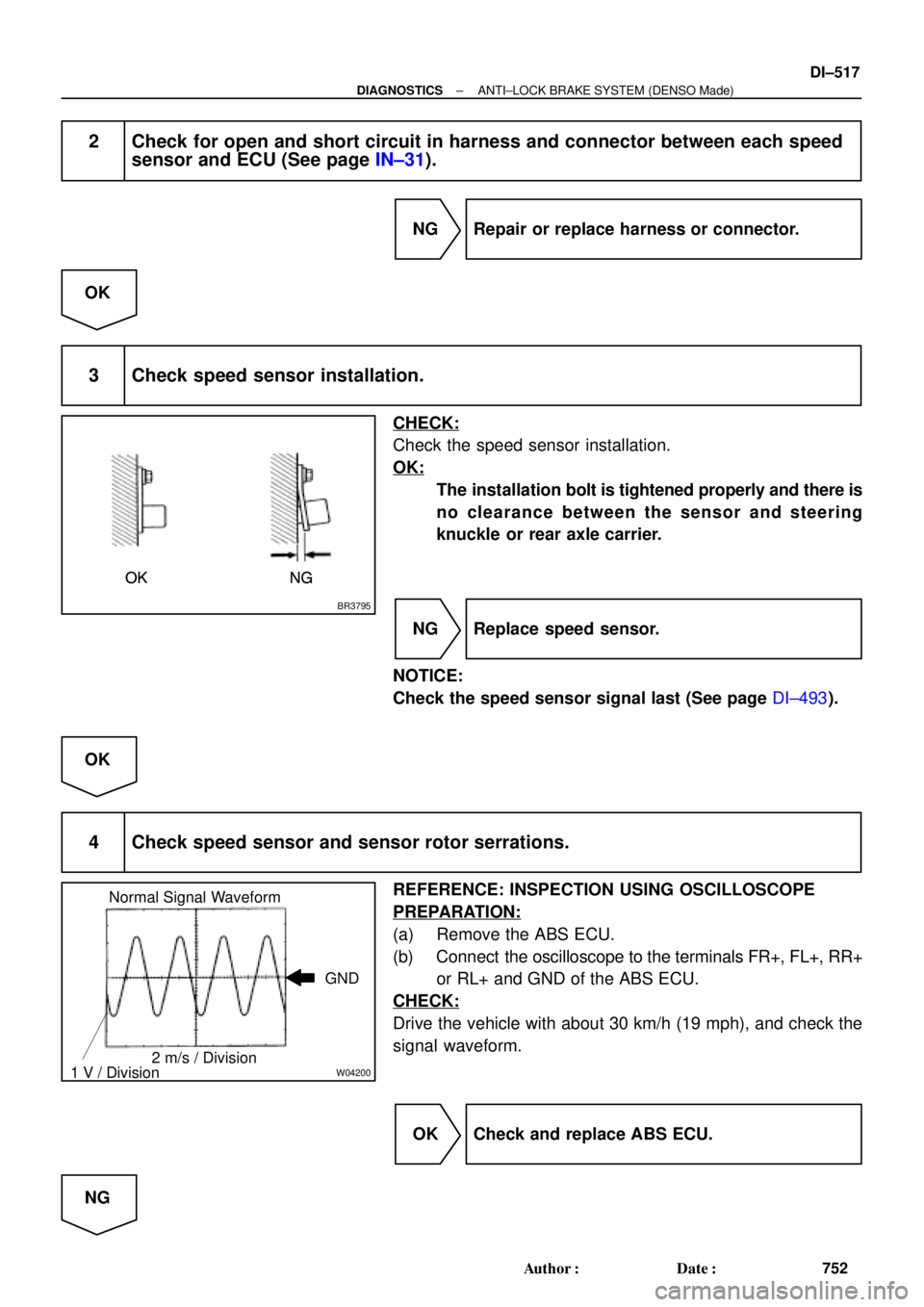
Normal Signal Waveform
1 V / Division2 m/s / DivisionGND
± DIAGNOSTICSANTI±LOCK BRAKE SYSTEM (DENSO Made)
DI±517
752 Author�: Date�:
2 Check for open and short circuit in harness and connector between each speed
sensor and ECU (See page IN±31).
NG Repair or replace harness or connector.
OK
3 Check speed sensor installation.
CHECK:
Check the speed sensor installation.
OK:
The installation bolt is tightened properly and there is
no clearance between the sensor and steering
knuckle or rear axle carrier.
NG Replace speed sensor.
NOTICE:
Check the speed sensor signal last (See page DI±493).
OK
4 Check speed sensor and sensor rotor serrations.
REFERENCE: INSPECTION USING OSCILLOSCOPE
PREPARATION:
(a) Remove the ABS ECU.
(b) Connect the oscilloscope to the terminals FR+, FL+, RR+
or RL+ and GND of the ABS ECU.
CHECK:
Drive the vehicle with about 30 km/h (19 mph), and check the
signal waveform.
OK Check and replace ABS ECU.
NG
Page 2938 of 4770
R00948
R00947
DI±518
± DIAGNOSTICSANTI±LOCK BRAKE SYSTEM (DENSO Made)
753 Author�: Date�:
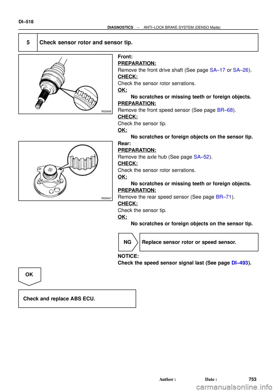
5 Check sensor rotor and sensor tip.
Front:
PREPARATION:
Remove the front drive shaft (See page SA±17 or SA±26).
CHECK:
Check the sensor rotor serrations.
OK:
No scratches or missing teeth or foreign objects.
PREPARATION:
Remove the front speed sensor (See page BR±68).
CHECK:
Check the sensor tip.
OK:
No scratches or foreign objects on the sensor tip.
Rear:
PREPARATION:
Remove the axle hub (See page SA±52).
CHECK:
Check the sensor rotor serrations.
OK:
No scratches or missing teeth or foreign objects.
PREPARATION:
Remove the rear speed sensor (See page BR±71).
CHECK:
Check the sensor tip.
OK:
No scratches or foreign objects on the sensor tip.
NG Replace sensor rotor or speed sensor.
NOTICE:
Check the speed sensor signal last (See page DI±493).
OK
Check and replace ABS ECU.
Page 2939 of 4770
± DIAGNOSTICSANTI±LOCK BRAKE SYSTEM (DENSO Made)
DI±519
754 Author�: Date�:
DTC 33, 34 Rear Speed Sensor Rotor Faulty
CIRCUIT DESCRIPTION
DTC No.DTC Detecting ConditionTrouble Area
33, 34
The condition that the both rear side wheels' speed is
lower than the front wheels' speed at 20 km/h (12 mph) or
more for 20 sec. or more when the IG switch turns ON
and OFF , which is repeated in a sequence more than 8
times.
�Rear axle hub
�Right rear, left rear speed sensor
�Rear speed sensor circuit
INSPECTION PROCEDURE
1 Check rear axle hub (See page SA±9).
NG Replace rear axle hub.
OK
2 Check rear speed sensor (See page DI±514).
NG Replace rear speed sensor.
OK
3 Check for open and short circuit in harness and connector between rear speed
sensor and ECU (See page IN±31).
NG Repair or replace harness and connector.
OK
Check and replace ABS ECU.
DI03L±03
Page 2943 of 4770

F00124
Battery MAIN B±GF4 F91
ALT FL Block
B±R STOP Instrument Panel J/B
1C1B4
7Stop Light
Switch
2G±W
1R 1S5J27 J28J/C
Light Failure
Sensor
J/C
J40
BL
BP W±BG±W
A195
STPABS ECU
R
G±R
High
Mounted
Stop
LightRight
Stop
LightLeft
Stop
Light
A 1Instrument
Panel J/B
G±R W
11R
2 4
G±W
G±R
W±B
W±B
W±B AAC
W±B W±BH10 R11
R9
H10R9
R11 2
122
5 5 G±W
1
2 7
Under the
Left Center
PillarBack Panel
Center
± DIAGNOSTICSANTI±LOCK BRAKE SYSTEM (DENSO Made)
DI±523
758 Author�: Date�:
DTC 49 Stop Light Switch Circuit
CIRCUIT DESCRIPTION
DTC No.DTC Detecting ConditionTrouble Area
49
ABS ECU terminal IG1 voltage is 9.5 V to 18.5 V and ABS
is in non±operation, the open circuit of the stop light switch
circuit continues for 0.3 sec. or more.�Stop light switch
�Stop light switch circuit
WIRING DIAGRAM
INSPECTION PROCEDURE
1 Check operation of stop light.
CHECK:
Check that stop light lights up when brake pedal is depressed and turns off when brake pedal is released.
NG Repair stop light circuit (See page BE±37).
OK
DI03N±03
Page 2954 of 4770
F00172
J/C
EC BRA
ABR
3
16 DLC1
Ts E
1
R±Y
II38
R±Y
A198
TsABS ECU
J22: (1MZ±FE)
J23: (5S±FE)
J/C
BRA
ABR
3
16 DLC1
Ts E
1
R±Y
II38
R±Y
A198
TsABS ECU
J22: (1MZ±FE)
J23: (5S±FE)
AB0119S08096
F00446DLC1 DLC1
DLC1
DLC1DLC1
Ts
DLC1 E1
ON
DI±534
± DIAGNOSTICSANTI±LOCK BRAKE SYSTEM (DENSO Made)
769 Author�: Date�:
Ts Terminal Circuit
CIRCUIT DESCRIPTION
The sensor check circuit detects abnormalities in the speed sensor signal which cannot be detected with
the DTC check.
Connecting terminals Ts and E
1 of the DLC1 in the engine compartment starts the check.
WIRING DIAGRAM
INSPECTION PROCEDURE
1 Check voltage between terminals Ts and E1 of DLC1.
CHECK:
(a) Turn the ignition switch ON.
(b) Measure voltage between terminals Ts and E
1 of DLC1.
OK:
Voltage: 10 ± 14 V
OK If ABS warning light does not blink even after Ts
and E
1 are connected, the ECU may be defec-
tive.
NG
DI03S±03
Page 2957 of 4770
DI051±04
Vehicle Brought to Workshop
Customer Problem Analysis
P. DI±538
Check and Clear DTC (Precheck)
P.
DI±539
Items inside
are titles of pages in this manual,
with the page number in the bottom portion. See
the pages for detailed explanations.
Problem Symptom ConfirmationSymptom Simulation
P. IN±21
Symptom
does not occur
Symptom
occurs
DTC Check
P. DI±539
Sensor CheckCircuit Inspection
P. DI±546 ~ DI±569
DTC Chart
P. DI±542 Malfunction codeProblem Symptoms Table
P. DI±545
Check for Fluid Leakage
P. DI±571
Identification of Problem
Normal code
Repair
Confirmation Test
End
1
2
3
4
5
67
89
10
11
Step 2, 5, 9, 11:Diagnostic steps permitting the use of the
TOYOTA hand±held tester.
± DIAGNOSTICSANTI±LOCK BRAKE SYSTEM (BOSCH Made)
DI±537
772 Author�: Date�:
ANTI±LOCK BRAKE SYSTEM (BOSCH Made)
HOW TO PROCEED WITH TROUBLESHOOTING
Troubleshoot in accordance with the procedure on the following pages.


J23: (5S±FE)
J/C
BRA
ABR
3
16 DLC1
Ts E
1
R±Y
II38
R±Y
A198
TsABS ECU
J22: (1MZ±FE)
J23: (5S±FE)
AB0119S08096
F")

P.
DI±539
Items inside
are titles of pages in this manual,
with the page number in the bot")