Page 2998 of 4770

DI04F±04
DI±578
± DIAGNOSTICSABS & TRACTION CONTROL SYSTEM
813 Author�: Date�:
DIAGNOSTIC TROUBLE CODE CHART
HINT:
�Using SST 09843 ±18020, connect the terminals Tc and E1.
�If a malfunction code is displayed during the DTC check, check the circuit listed for the code. For details
of each code, turn to the page referred to under the ºSee pageº for respective ºDTC No.º in the DTC
chart.
DTC No.
(See Page)Detection ItemTrouble Area
11
(DI±584)Open circuit in ABS & TRAC solenoid relay circuit�ABS & TRAC solenoid relay
ABS & TRAC l id l i it12
(DI±584)Short circuit in ABS & TRAC solenoid relay circuit
�ABS & TRAC solenoid relay circuit
�ECU
13
(DI±587)Open circuit in ABS & TRAC motor relay circuit�ABS & TRAC motor relay
ABS & TRAC t l i it14
(DI±587)Short circuit in ABS & TRAC motor relay circuit
�ABS & TRAC motor relay circuit
�ECU
21
(DI±590)Open or short circuit in right front solenoid circuit
�ABS & TRAC actuator
�SFRR or SFRH circuit
�ECU
22
(DI±590)Open or short circuit in left front solenoid circuit
�ABS & TRAC actuator
�SFLR or SFLH circuit
�ECU
23
(DI±590)Open or short circuit in right rear solenoid circuit
�ABS & TRAC actuator
�SRRR or SRRH circuit
�ECU
24
(DI±590)Open or short circuit in left rear solenoid circuit
�ABS & TRAC actuator
�SRLR or SRLH circuit
�ECU
25
(DI±590)Open or short circuit in SMC1 circuit
�ABS & TRAC actuator
�SMC1 circuit
�ECU
26
(DI±590)Open or short circuit in SMC2 circuit
�ABS & TRAC actuator
�SMC2 circuit
�ECU
27
(DI±590)Open or short circuit in SRC1 circuit
�ABS & TRAC actuator
�SRC1 circuit
�ECU
28
(DI±590)Open or short circuit in SRC2 circuit
�ABS & TRAC actuator
�SRC2 circuit
�ECU
31
(DI±593)Right front wheel speed sensor signal malfunction
32
(DI±593)Left front wheel speed sensor signal malfunction�Right front, left front, right rear and left rear speed sensor
�Each speed sensor circuit
33
(DI±593)Right rear wheel speed sensor signal malfunction
�Each s eed sensor circuit
�Speed sensor rotor
�ECU
34
(DI±593)Left rear wheel speed sensor signal malfunction
41
(DI±598)Low battery positive voltage or abnormally high battery
positive voltage
�Battery
�Charging system
�Power source circuit
�ECU
Page 3000 of 4770
DI04G±04
F01177
SLIP Indicator Light
TRAC OFF Indicator Light
ABS Warning Light
DLC1
DLC2
Rear Speed Sensor
Sensor Rotor ABS & TRAC ActuatorABS & TRAC ECU
TRAC OFF Switch
ABS & TRAC
Solenoid Relay
ABS & TRAC
Motor RelaySensor Rotor
Front Speed Sensor
Stop Light Switch Front Speed Sensor
DI±580
± DIAGNOSTICSABS & TRACTION CONTROL SYSTEM
815 Author�: Date�:
PARTS LOCATION
Page 3003 of 4770

DI04I±04
± DIAGNOSTICSABS & TRACTION CONTROL SYSTEM
DI±583
818 Author�: Date�:
PROBLEM SYMPTOMS TABLE
If a normal code is displayed during the DTC check but the problem still occurs, check the circuits for each
problem symptom in the order given in the table below and proceed to the relevant troubleshooting page.
SymptomSuspect AreaSee page
ABS does not operate.
Only when 1. to 4. are all normal and the problem is still
occurring, replace the
ABS & TRAC ECU.
1. Check the DTC reconfirming that the normal code is
output.
2. IG power source circuit
3. Speed sensor circuit
4. Check the ABS & TRAC actuator with a checker. If ab-
normal, check the hydraulic circuit for leakage
(See page DI±623).
DI±574
DI±598
DI±593
BR±61
ABS does not operate efficiently.
Only when 1. to 4. are all normal and the problem is still
occurring, replace the
ABS & TRAC ECU.
1. Check the DTC reconfirming that the normal code is
output.
2. Speed sensor circuit.
3. Stop light switch circuit.
4. Check the ABS & TRAC actuator with a checker. If ab-
normal, check the hydraulic circuit for leakage
(See page DI±623).
DI±574
DI±593
DI±604
BR±61
ABS warning light abnormal.1. ABS warning light circuit
2. ABS & TRAC ECUDI±612
DI±610
DTC check cannot be done.
Only when 1. and 2. are all normal and the problem is still
occurring, replace the ABS & TRAC ECU.
1. ABS warning light circuit
2. TRAC OFF indicator light circuit
3. Tc terminal circuit
DI±612
DI±617
DI±621
Speed sensor signal check cannot be done.1. Ts terminal circuit
2. ABS & TRAC ECUDI±615
DI±610
TRAC does not operate.
Only when inspection circuits for each problem symptom
are all normal and the problem is still occurring, replace the
ABS & TRAC ECU.
1. Check the DTC, reconfirming that the normal code is
output.
2. IG power source circuit
3. Check the hydraulic circuit for leakage
4. Speed sensor circuit
DI±574
DI±598
DI±623
DI±593
SLIP indicator light abnormal.SLIP indicator light circuitDI±620
TRAC OFF indicator light abnormal.
Only when inspection circuits for each problem symptom
are all normal and the problem is still occurring, replace the
ABS & TRAC ECU.
1. TRAC OFF indicator light circuit
2. TRAC cut switch circuit
DI±617
DI±617
Page 3013 of 4770

BR3583
BR3582F00010
RotorSpeed Sensor
Magnet
To ECU
+V
±VHigh Speed
Low Speed
CoilNS
± DIAGNOSTICSABS & TRACTION CONTROL SYSTEM
DI±593
828 Author�: Date�:
DTC31, 32, 33, 34Speed Sensor Circuit
CIRCUIT DESCRIPTION
The speed sensor detects wheel speed and sends the ap-
propriate signals to the ECU. These signals are used to control
the ABS and TRAC system. The front and rear rotors each have
48 serrations.
When the rotors rotate, the magnetic field emitted by the perma-
nent magnet in the speed sensor generates an AC voltage.
Since the frequency of this AC voltage changes in direct propor-
tion to the speed of the rotor, the frequency is used by the ECU
to detect the speed of each wheel.
DTC No.DTC Detecting ConditionTrouble Area
31, 32, 33, 34
Detection of any of conditions from 1. through 3.:
1. ABS is in non±operation, wheel speed is 10 km/h or
more, one eighth of maximum wheel speed is greater
than the minimum wheel speed, one eighth of maximum
wheel speed is smaller than the rear maximum wheel
speed or momentary interruption of both the rear wheels
are shown in the 15 sec. or more continuously.
2. ABS is in non±operation, momentary interruption of
speed sensor occurs 7 times or more in the mean time
of switching the ignition switch ON and OFF or vehicle
speed is 20 km/h (12 mph) or more and the condition of
noise interference or non±noise interference occurs 75
times or more within 5 sec.
3. Vehicle is at a stop, malfunction signal of vehicle speed
sensor hardware open circuit is ON for 1.02 sec. contin-
uously since starting the checking of a certain vehicle.
�Right front, left front, right rear, left rear speed sensor
�Each speed sensor circuit
�Speed sensor rotor
�ECU
HINT:
�DTC No. 31 is for the right front speed sensor.
�DTC No. 32 is for the left front speed sensor.
�DTC No. 33 is for the right rear speed sensor.
�DTC No. 34 is for the left rear speed sensor.
Fail safe function:
If any trouble occurs in the speed sensor circuit, the ECU cuts off current to the ABS & TRAC solenoid relay
and prohibits ABS control and TRAC control.
DI1JP±03
Page 3014 of 4770
F00116
ABS & TRAC ECU
A15
A16 B
G6W
12
R
IK2
IL1 Left Front
Speed SensorRight Front
Speed Sensor
B
G R
Left Rear
Speed Sensor Right Rear
Speed Sensor2
1
1
2
2
1A15
A15
A15
A16
A16
A16 R
IK21
G
W
IL11 2FR+
FL+
FL±
RR+ 17
RL+
RL± 4 18
5FR±
RR± 10
ID19
ID12
1 93ABS & TRAC ECU
A15
A16 B
G6W
12
R
IK2
IL1 Right Front
Speed Sensor
B
W
*1
G R
Left Rear
Speed Sensor2
1
1
2
2
1A15
A15
A15
A16
A16
A16 R
IK21
G
W
IL11 2FR+
FL+
FL±
RR+ 17
RL+
RL± 4 18
5FR±
RR± 10
ID19
ID12
1 93
Y
*2
G*1
BR*2
B*1
Y*2
W*1
P*2
*1
: TMC Made*2: TMMK Made DI±594
± DIAGNOSTICSABS & TRACTION CONTROL SYSTEM
829 Author�: Date�:
WIRING DIAGRAM
Page 3015 of 4770
R14205
1
2
R14213
12
12
12
12
12
1212
± DIAGNOSTICSABS & TRACTION CONTROL SYSTEM
DI±595
830 Author�: Date�:
INSPECTION PROCEDURE
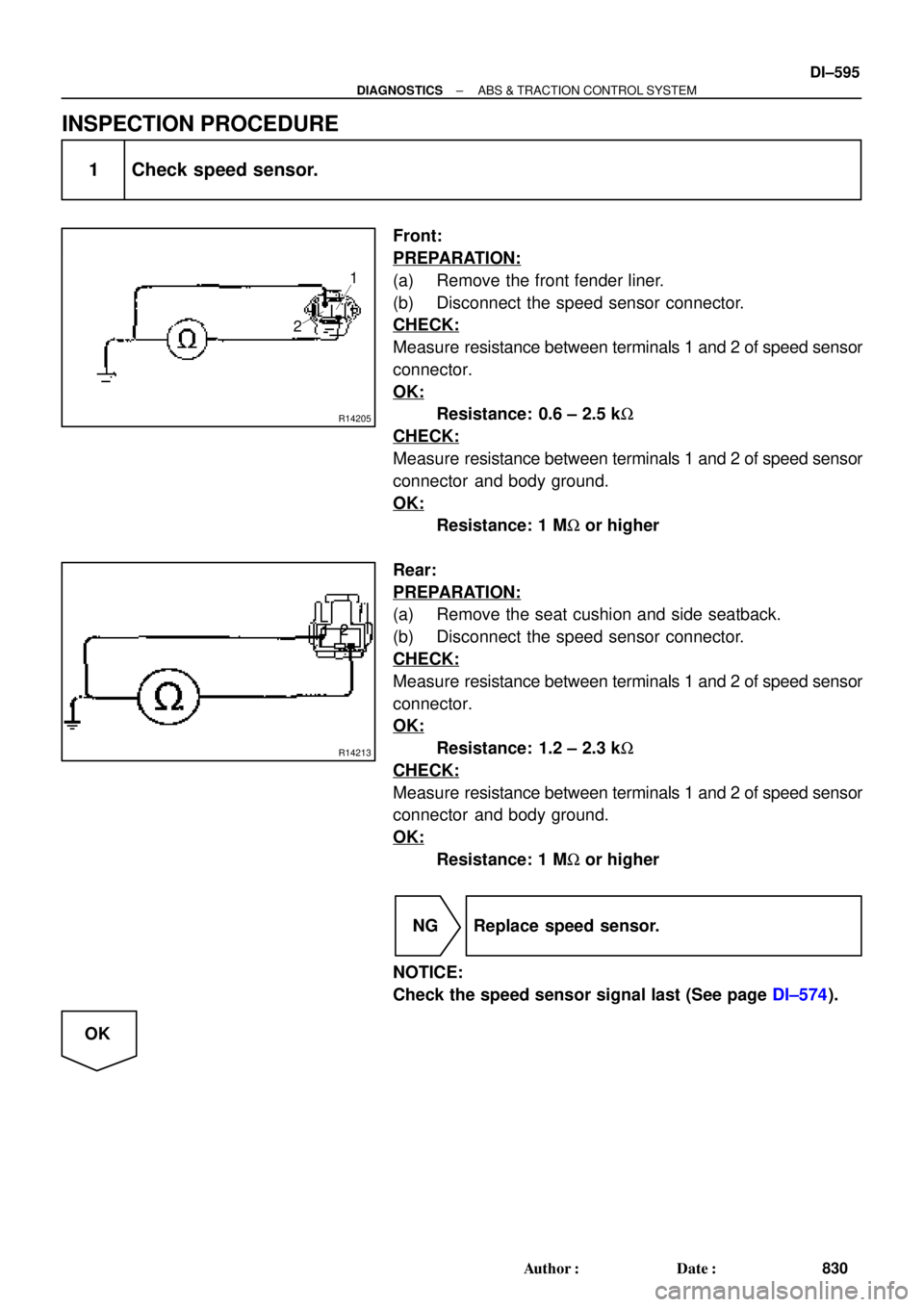
1 Check speed sensor.
Front:
PREPARATION:
(a) Remove the front fender liner.
(b) Disconnect the speed sensor connector.
CHECK:
Measure resistance between terminals 1 and 2 of speed sensor
connector.
OK:
Resistance: 0.6 ± 2.5 kW
CHECK:
Measure resistance between terminals 1 and 2 of speed sensor
connector and body ground.
OK:
Resistance: 1 MW or higher
Rear:
PREPARATION:
(a) Remove the seat cushion and side seatback.
(b) Disconnect the speed sensor connector.
CHECK:
Measure resistance between terminals 1 and 2 of speed sensor
connector.
OK:
Resistance: 1.2 ± 2.3 kW
CHECK:
Measure resistance between terminals 1 and 2 of speed sensor
connector and body ground.
OK:
Resistance: 1 MW or higher
NG Replace speed sensor.
NOTICE:
Check the speed sensor signal last (See page DI±574).
OK
Page 3016 of 4770
BR3795
OK NG OK NG
OK NGOK NG
W04200
Normal Signal Waveform
1 V / Division2 m/s / DivisionGND
DI±596
± DIAGNOSTICSABS & TRACTION CONTROL SYSTEM
831 Author�: Date�:
2 Check for open and short circuit in harness and connector between each speed
sensor and ECU (See page IN±31).
NG Repair or replace harness or connector.
OK
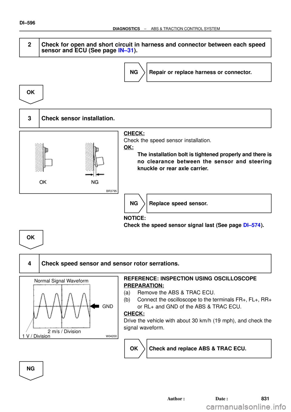
3 Check sensor installation.
CHECK:
Check the speed sensor installation.
OK:
The installation bolt is tightened properly and there is
no clearance between the sensor and steering
knuckle or rear axle carrier.
NG Replace speed sensor.
NOTICE:
Check the speed sensor signal last (See page DI±574).
OK
4 Check speed sensor and sensor rotor serrations.
REFERENCE: INSPECTION USING OSCILLOSCOPE
PREPARATION:
(a) Remove the ABS & TRAC ECU.
(b) Connect the oscilloscope to the terminals FR+, FL+, RR+
or RL+ and GND of the ABS & TRAC ECU.
CHECK:
Drive the vehicle with about 30 km/h (19 mph), and check the
signal waveform.
OK Check and replace ABS & TRAC ECU.
NG
Page 3017 of 4770
R00948
R00947
± DIAGNOSTICSABS & TRACTION CONTROL SYSTEM
DI±597
832 Author�: Date�:
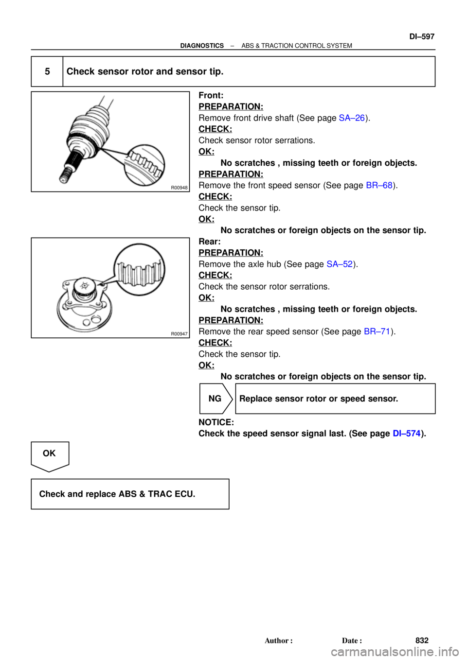
5 Check sensor rotor and sensor tip.
Front:
PREPARATION:
Remove front drive shaft (See page SA±26).
CHECK:
Check sensor rotor serrations.
OK:
No scratches , missing teeth or foreign objects.
PREPARATION:
Remove the front speed sensor (See page BR±68).
CHECK:
Check the sensor tip.
OK:
No scratches or foreign objects on the sensor tip.
Rear:
PREPARATION:
Remove the axle hub (See page SA±52).
CHECK:
Check the sensor rotor serrations.
OK:
No scratches , missing teeth or foreign objects.
PREPARATION:
Remove the rear speed sensor (See page BR±71).
CHECK:
Check the sensor tip.
OK:
No scratches or foreign objects on the sensor tip.
NG Replace sensor rotor or speed sensor.
NOTICE:
Check the speed sensor signal last. (See page DI±574).
OK
Check and replace ABS & TRAC ECU.