Page 2747 of 4770
± DIAGNOSTICSENGINE (1MZ±FE)
DI±327
562 Author�: Date�:
3 Check voltage between terminals VC and E2 of ECM connector
(See page DI±311, step 9).
NG Check and replace ECM (See page IN±31).
OK
4 Check voltage between terminals PTNK and E2 of ECM connectors
(See page DI±311, step 10).
OK Go to step 6.
NG
5 Check for open and short in harness and connector between vapor pressure
sensor and ECM (See page IN±31).
NG Repair or replace harness or connector.
OK
Replace vapor pressure sensor.
Page 2749 of 4770
A07149
ON
TPC
OFFON
VSV is ON
VSV is OFF
Air
E
FG Air
G E
F
± DIAGNOSTICSENGINE (1MZ±FE)
DI±329
564 Author�: Date�:
8 Check for open and short in harness and connector between EFI main relay
(Marking: EFI) and VSV for EVAP and ECM (See page IN±31).
NG Repair or replace harness or connector.
OK
Check and replace ECM (See page IN±31).
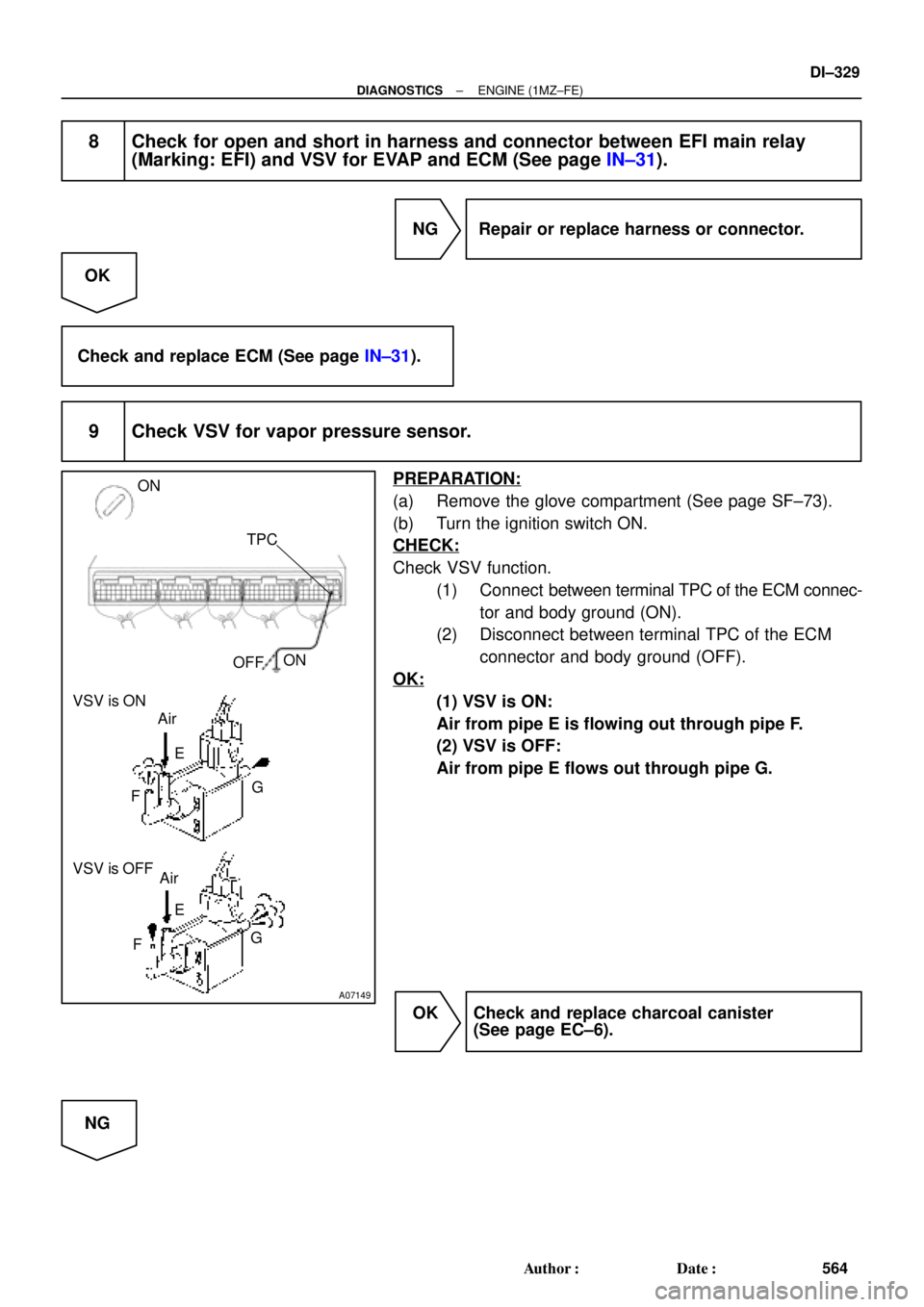
9 Check VSV for vapor pressure sensor.
PREPARATION:
(a) Remove the glove compartment (See page SF±73).
(b) Turn the ignition switch ON.
CHECK:
Check VSV function.
(1) Connect between terminal TPC of the ECM connec-
tor and body ground (ON).
(2) Disconnect between terminal TPC of the ECM
connector and body ground (OFF).
OK:
(1) VSV is ON:
Air from pipe E is flowing out through pipe F.
(2) VSV is OFF:
Air from pipe E flows out through pipe G.
OK Check and replace charcoal canister
(See page EC±6).
NG
Page 2750 of 4770
DI±330
± DIAGNOSTICSENGINE (1MZ±FE)
565 Author�: Date�:
10 Check operation of VSV for vapor pressure sensor (See page SF±62).
OK Go to step 11.
NG
Replace VSV and clean the vacuum hoses between charcoal canister and VSV for vapor pressure
sensor, and VSV for vapor pressure sensor and vapor pressure sensor, and then check the char-
coal canister.
11 Check for open and short in harness and connector between EFI main relay
(Marking: EFI) and VSV for vapor pressure sensor, and VSV for vapor pressure
sensor and ECM (See page IN±31).
NG Repair or replace harness or connector.
OK
Check and replace ECM (See page IN±31).
12 Check the fuel tank over fill check valve (See page EC±6).
NG Replace fuel tank over fill check valve or fuel
tank.
OK
Check and replace charcoal canister
(See page EC±6).
Page 2751 of 4770

DI±331
566 Author�: Date�:
DTC P04")
A01655
Charcoal CanisterVapor Pressure
Sensor
VSV for Vapor
Pressure Sensor
Fuel Tank VSV
for EVAPECM
Fuel Tank Over
Fill Check Valve
± DIAGNOSTICSENGINE (1MZ±FE)
DI±331
566 Author�: Date�:
DTC P0450 Evaporative Emission Control System
Pressure Sensor Malfunction
DTC P0451 Evaporative Emission Control System
Pressure Sensor Range/Performance
CIRCUIT DESCRIPTION
The vapor pressure sensor and VSV for vapor pressure sensor are used to detect abnormalities in the evap-
orative emission control system.
The ECM decides whether there is an abnormality in the evaporative emission control system based on the
vapor pressure sensor signal.
DTC P0450 or p0451 is recorded by the ECM when the vapor pressure sensor malfunction.
DTC No.DTC Detecting ConditionTrouble Area
P0450
10 seconds or more after engine starting condition (a) or (b)
continues for 7 seconds or more:
(2 trip detection logic)
(a) Vapor Pressure Sensor Value
< ±3.5 kPa (±26 mmHg,
±1.0 in.Hg)
(b) Vapor Pressure Sensor Value � 1.5 kPa (15 mmHg,
0.4 in.Hg)
�Open or short in vapor pressure sensor circuit
V
P451
Vapor pressure sensor output extremely changes under
conditions of (a), (b) and (c):
(2 trip detection logic)
(a) Vehicle speed: 0 km/h (0 mph)
(b) Engine speed: Idling
(c) VSV for vapor pressure sensor is ON.�Vapor pressure sensor
�ECM
DI1K5±03
Page 2752 of 4770

567 Author�: Date�:
WIRING DIAGRAM
Refer to DTC P0440 (Evaporative Emission Control Malfunction) on page DI±311.
INSPECTION PROCEDURE
HINT:
�If DTCs P0441, P044")
DI±332
± DIAGNOSTICSENGINE (1MZ±FE)
567 Author�: Date�:
WIRING DIAGRAM
Refer to DTC P0440 (Evaporative Emission Control Malfunction) on page DI±311.
INSPECTION PROCEDURE
HINT:
�If DTCs P0441, P0446, P0450 or P0451 is output after DTC P0440, first troubleshoot DTCs P0441,
P0446 ,P0450 or P0451. If no malfunction is detected, troubleshoot DTC P0440 next.
�Read freeze frame data using TOYOTA hand±held tester or OBD II scan tool. Because freeze frame
records the engine conditions when the malfunction is detected, when troubleshooting it is useful for
determining whether the vehicle was running or stopped, the engine warmed up or not, the air±fuel
ratio lean or rich, etc. at the time of the malfunction.
�When the ENGINE RUN TIME in the freeze frame data is less than 200 seconds, carefully check the
VSV for EVAP, charcoal canister and vapor pressure sensor.
1 Check voltage between terminals VC and E2 of ECM connector
(See page DI±311, step 9).
NG Check and replace ECM (See page IN±31).
OK
2 Check voltage between terminals PTNK and E2 of ECM connectors
(See page DI±311, step 10).
OK Check and replace ECM (See page IN±31).
NG
3 Check for open and short in harness and connector between vapor pressure
sensor and ECM (See page IN±31).
NG Repair or replace harness or connector.
OK
Replace vapor pressure sensor.
Page 2753 of 4770

A00223
Vehicle Speed
Sensor
Combination
Meter
ECM
Transaxle4±Pulse 4±Pulse
Vehicle Speed Sensor
Q00515 Q00514
A03316
Combination
MeterJ15
Junction
Connector
14
C93
V±W V±W V±WECM
SPD5V
BBE8 22
IG3
± DIAGNOSTICSENGINE (1MZ±FE)
DI±333
568 Author�: Date�:
DTC P0500 Vehicle Speed Sensor Malfunction
CIRCUIT DESCRIPTION
The vehicle speed sensor outputs a 4±pulse signal for every revolution of the rotor shaft, which is rotated
by the transmission output shaft via the driven gear. After this signal is converted into a more precise rectan-
gular waveform by the waveform shaping circuit inside the combination meter, it is then transmitted to the
ECM. The ECM determines the vehicle speed based on the frequency of these pulse signals.
DTC No.DTC Detecting ConditionTrouble Area
P0500
No vehicle speed sensor signal to ECM under conditions (a)
and (b):
(2 trip detection logic)
(a) Park/neutral position switch is OFF
(b) Vehicle is being driven�Open or short in vehicle speed sensor circuit
�Vehicle speed sensor
�Combination meter
�ECM
WIRING DIAGRAM
DI082±06
Page 2754 of 4770

569 Author�: Date�:
INSPECTION PROCEDURE
HINT:
Read freeze frame data using TOYOTA hand±held tester or OBD II scan tool. Because freeze frame reco")
A02030
SPD
E8
DI±334
± DIAGNOSTICSENGINE (1MZ±FE)
569 Author�: Date�:
INSPECTION PROCEDURE
HINT:
Read freeze frame data using TOYOTA hand±held tester or OBD II scan tool. Because freeze frame records
the engine conditions when the malfunction is detected, when troubleshooting it is useful for determining
whether the vehicle was running or stopped, the engine warmed up or not, the air±fuel ratio lean or rich, etc.
at the time of the malfunction.
1 Check operation of speedometer.
CHECK:
Drive the vehicle and check if the operation of the speedometer in the combination meter is normal.
HINT:
The vehicle speed sensor is operating normally if the speedmeter display is normal.
NG Check speedmeter circuit.
OK
2 Check for short in harness and connector between terminal SPD of ECM and
body ground (See page IN±31).
PREPARATION:
(a) Remove the glove compartment (See page SF±73).
(b) Disconnect the E8 connector of ECM.
CHECK:
Check continuity between terminal SPD of ECM and body
ground.
OK:
No continuity (1 MW or higher)
NG Repair or replace harness or connector.
OK
Page 2760 of 4770

575 Author�: Date�:
DTC P1130 A/F Sensor Circuit Range/Performance Mal-
function (Only for California Spec.)
DTC P1150 A/F Sensor Circuit Range/Performance Mal-")
DI±340
± DIAGNOSTICSENGINE (1MZ±FE)
575 Author�: Date�:
DTC P1130 A/F Sensor Circuit Range/Performance Mal-
function (Only for California Spec.)
DTC P1150 A/F Sensor Circuit Range/Performance Mal-
function (Only for California Spec.)
CIRCUIT DESCRIPTION
Refer to DTC P0125 (Insufficient Temp. for Closed Loop Fuel Control (Only for California Spec.)) on Page
DI±249.
DTC No.DTC Detecting ConditionTrouble Area
Voltage output* of A/F sensor remains at 3.8 V or more, or
2.8 V or less, during engine running after engine is warmed
up (2 trip detection logic)
*: Output value changes at inside of ECM only.
P1130
P1150Voltage output* of A/F sensor does not change from 3.30 V,
during engine running after engine is warmed up
(2 trip detection logic)
*: Output value changes at inside of ECM only.�Open or short in A/F sensor (bank 1, 2 sensor 1) circuit
�A/F sensor (bank 1, 2 sensor 1)
�ECM
Open or short in A/F sensor circuit
(2 trip detection logic)
HINT:
�After confirming DTC P1130 or P01150, use the OBD II scan tool or TOYOTA hand±held tester to con-
firm voltage output of A/F sensor (AFS B1 S1/O2S B1 S1) from ºCURRENT DATAº.
�The A/F sensor's output voltage and the short±term fuel value can be read using the OBD II scan tool
or TOYOTA hand±held tester.
�The ECM controls the voltage of AFR/AFL� and AFR/AFL� terminals of ECM to the fixed voltage.
Therefore, it is impossible to confirm the A/F sensor output voltage without OBD II scan tool or TOYOTA
hand±held tester.
�OBD II scan tool (excluding TOYOTA hand±held tester) displays the one fifth of the A/F sensor output
voltage which is displayed on the TOYOTA hand±held tester.
WIRING DIAGRAM
Refer to DTC P0125 (Insufficient Coolant Temp. for Closed Loop Fuel Control (Only for California Spec.))
on page DI±249.
DI1K6±03