Page 2713 of 4770
A07446
J20
Junction
Connector
EFI Relay
2K2J
2C
BB±YJ27 J28
W±B
EB
9B±Y Y±G
AA1218
13 1
2
G±Y
BRECM
EGR
E01
EGLS5 V
E2 32
VC
5 V
THG
E7
2
1W±GY
BR18
8
MREL
B+ BR
EGR Gas Temp. Sensor
E10 E10
22
E11 E10E11
Engine Room J/B
2A2
7 1
53
1 5
EFI
VSV
for EGR
B±Y
Junction
Connector
B
2
B±Y
J35
J35C
C Junction
ConnectorB±W
B±W
B±W
EGR Valve
Position Sensor
II3From
FL MAIN
S06906
Vehicle Speed
70 ~ 90 km/h
(43 ~ 56 mph)
Idling
IG SW OFF(1)(2)(3)
(4)(5)
Warmed up 3 ~ 5 min. 3 min. 3 ~ 5 min. 2 min.Time
± DIAGNOSTICSENGINE (1MZ±FE)
DI±293
528 Author�: Date�:
WIRING DIAGRAM
SYSTEM CHECK DRIVING PATTERN
Page 2715 of 4770
A00305
ON
ON EGR Gas Temp.
Sensor
EGR Gas Temp.
SensorECM
ECM
5 V
5 V
E2
E2
1
2
1
2
THG
THG18 13
E10
E10
E10E10
13
18
± DIAGNOSTICSENGINE (1MZ±FE)
DI±295
530 Author�: Date�:
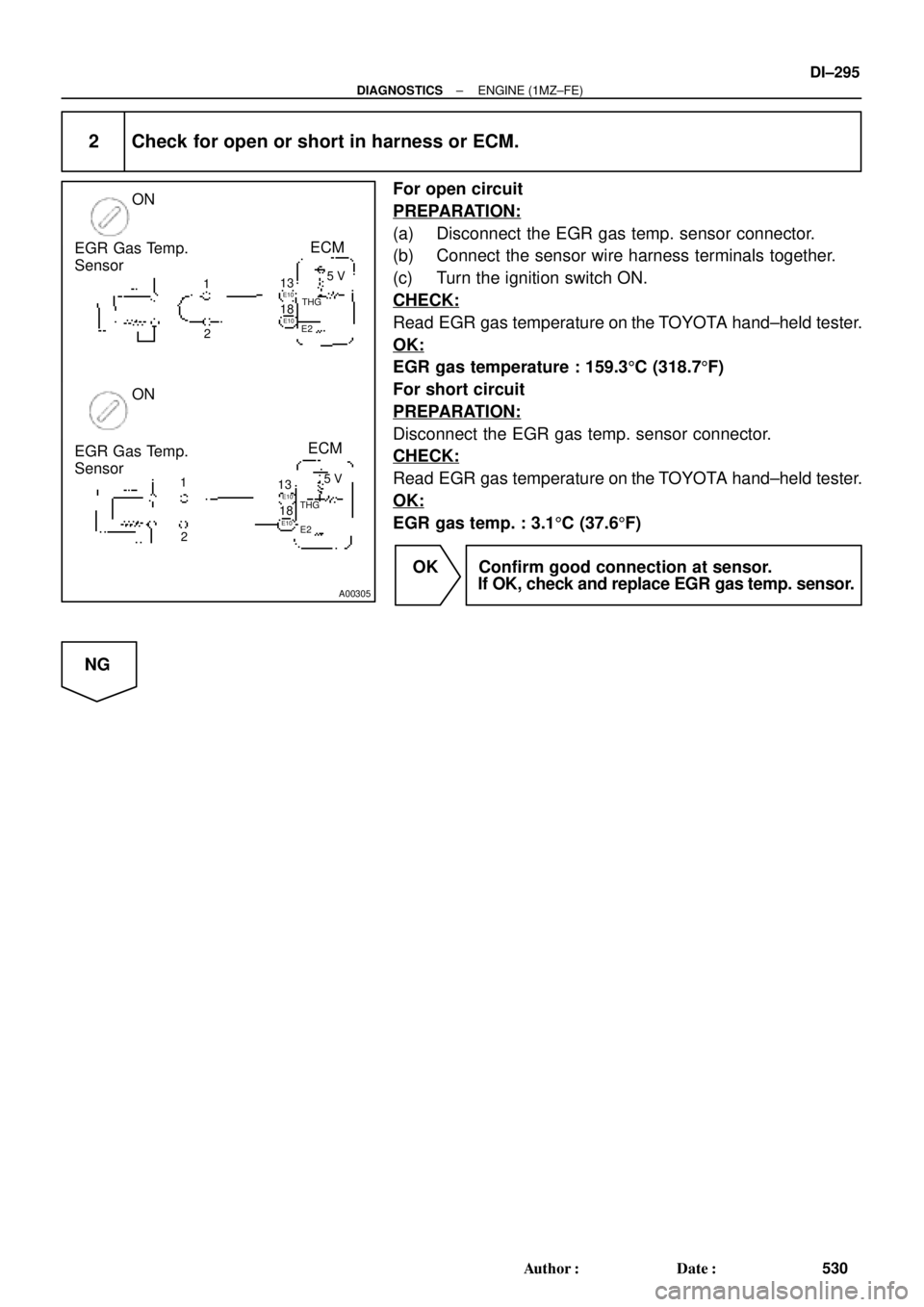
2 Check for open or short in harness or ECM.
For open circuit
PREPARATION:
(a) Disconnect the EGR gas temp. sensor connector.
(b) Connect the sensor wire harness terminals together.
(c) Turn the ignition switch ON.
CHECK:
Read EGR gas temperature on the TOYOTA hand±held tester.
OK:
EGR gas temperature : 159.35C (318.75F)
For short circuit
PREPARATION:
Disconnect the EGR gas temp. sensor connector.
CHECK:
Read EGR gas temperature on the TOYOTA hand±held tester.
OK:
EGR gas temp. : 3.15C (37.65F)
OK Confirm good connection at sensor.
If OK, check and replace EGR gas temp. sensor.
NG
Page 2716 of 4770
A02048
ECM
THG E2ON
1
2E0
E107THG
E2 13
18 EGR Gas Temp. Sensor
5 V
A02043
ECM ON
EGR Gas Temp. Sensor
E10
5 V
THG
E2
DI±296
± DIAGNOSTICSENGINE (1MZ±FE)
531 Author�: Date�:
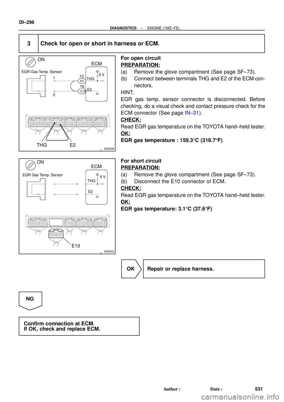
3 Check for open or short in harness or ECM.
For open circuit
PREPARATION:
(a) Remove the glove compartment (See page SF±73).
(b) Connect between terminals THG and E2 of the ECM con-
nectors.
HINT:
EGR gas temp. sensor connector is disconnected. Before
checking, do a visual check and contact pressure check for the
ECM connector (See page IN±31).
CHECK:
Read EGR gas temperature on the TOYOTA hand±held tester.
OK:
EGR gas temperature : 159.35C (318.75F)
For short circuit
PREPARATION:
(a) Remove the glove compartment (See page SF±73).
(b) Disconnect the E10 connector of ECM.
CHECK:
Read EGR gas temperature on the TOYOTA hand±held tester.
OK:
EGR gas temperature: 3.15C (37.65F)
OK Repair or replace harness.
NG
Confirm connection at ECM.
If OK, check and replace ECM.
Page 2719 of 4770
P23871
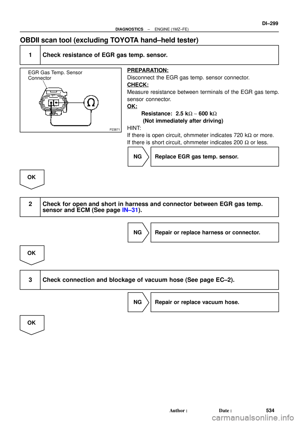
EGR Gas Temp. Sensor
Connector
± DIAGNOSTICSENGINE (1MZ±FE)
DI±299
534 Author�: Date�:
OBDII scan tool (excluding TOYOTA hand±held tester)
1 Check resistance of EGR gas temp. sensor.
PREPARATION:
Disconnect the EGR gas temp. sensor connector.
CHECK:
Measure resistance between terminals of the EGR gas temp.
sensor connector.
OK:
Resistance: 2.5 kW ~ 600 kW
(Not immediately after driving)
HINT:
If there is open circuit, ohmmeter indicates 720 kW or more.
If there is short circuit, ohmmeter indicates 200 W or less.
NG Replace EGR gas temp. sensor.
OK
2 Check for open and short in harness and connector between EGR gas temp.
sensor and ECM (See page IN±31).
NG Repair or replace harness or connector.
OK
3 Check connection and blockage of vacuum hose (See page EC±2).
NG Repair or replace vacuum hose.
OK
Page 2722 of 4770

537 Author�: Date�:
DTC P0402 Exhaust Gas Recirculation Flow
Excessive Detected (Ex CA Spec.)
CIRCUIT DESCRIPTION
Refer to DTC P0401 (Exhaust Gas Recirculation")
DI±302
± DIAGNOSTICSENGINE (1MZ±FE)
537 Author�: Date�:
DTC P0402 Exhaust Gas Recirculation Flow
Excessive Detected (Ex CA Spec.)
CIRCUIT DESCRIPTION
Refer to DTC P0401 (Exhaust Gas Recirculation Flow Insufficient Detected) on page DI±292.
DTC No.DTC Detecting ConditionTrouble Area
P0402
When EGR cut±off, lift amount of EGR valve is
2.6 mm (0.1 in.) or more
(2 trip detection logic)
�EGR valve stuck open
�VSV for EGR open malfunction
�Short in VSV circuit for EGR
�Open or short in EGR valve position sensor circuit
�EGR valve position sensor
�ECM
See DTC P0401 (Exhaust Gas Recirculation Flow Insufficient Detected) on See page DI±292 for SYS-
TEM CHECK DRIVING PATTERN and WIRING DIAGRAM.
INSPECTION PROCEDURE
HINT:
Read freeze frame data using TOYOTA hand±held tester or OBD II scan tool. Because freeze frame records
the engine conditions when the malfunction is detected, when troubleshooting it is useful for determining
whether the vehicle was running or stopped, the engine warmed up or not, the air±fuel ratio lean or rich, etc.
at the time of the malfunction.
TOYOTA hand±held tester
1 Check connection and blockage of vacuum hose.
NG Repair or replace vacuum hose.
OK
2 Check VSV for EGR (See page DI±292, step 5).
OK Go to step 4.
NG
DI07X±06
Page 2723 of 4770
± DIAGNOSTICSENGINE (1MZ±FE)
DI±303
538 Author�: Date�:
3 Check operation of VSV for EGR (See page SF±56).
NG Replace VSV for EGR.
OK
Check for short in harness between VSV for
EGR and ECM (See page IN±31).
4 Check EGR valve (See page EC±11).
NG Repair or replace EGR valve.
OK
5 Check EGR valve position sensor (See page DI±358).
NG Repair or replace EGR valve position sensor or
harness.
OK
Check and replace ECM (See page IN±31).
OBDII scan tool (excluding TOYOTA hand±held tester)
1 Check connection and blockage of vacuum hose.
NG Repair or replace vacuum hose.
OK
Page 2724 of 4770
DI±304
± DIAGNOSTICSENGINE (1MZ±FE)
539 Author�: Date�:
2 Check VSV for EGR (See page DI±292, step 5).
OK Go to step 4.
NG
3 Check operation of VSV for EGR (See page SF±56).
NG Replace VSV for EGR.
OK
Check for short in harness between VSV for
EGR and ECM (See page IN±31).
4 Check EGR valve (See page EC±11).
NG Repair or replace EGR valve.
OK
5 Check EGR valve position sensor (See page DI±358).
NG Repair or replace EGR valve position sensor or
harness.
OK
Check and replace ECM (See page IN±31).
Page 2725 of 4770
(b)(c) (d)
Time Warmed up 3 min. or so")
FI7081
Waveform of Oxygen Sensor
before CatalystNormal Catalyst Waveform of Oxygen Sensor
after Catalyst
FI7132
Engine Speed
2,500 ~ 3,000 rpm
Idling
IG SW OFF(a)(b)(c) (d)
Time Warmed up 3 min. or so Check
± DIAGNOSTICSENGINE (1MZ±FE)
DI±305
540 Author�: Date�:
DTC P0420 Catalyst System Efficiency Below Threshold
(Except California Spec.)
CIRCUIT DESCRIPTION
The ECM compares the waveform of the oxygen sensor located before the catalyst with the waveform of
the oxygen sensor located after the catalyst to determine whether or not catalyst performance has deterio-
rated.
Air±fuel ratio feedback compensation keeps the waveform of the oxygen sensor before the catalyst repeat-
edly changing back and forth from rich to lean.
If the catalyst is functioning normally, the waveform of the oxygen sensor after the catalyst switches back
and forth between rich and lean much more slowly than the waveform of the oxygen sensor before the cata-
lyst.
But when both waveforms change at a similar rate, it indicates that catalyst performance has deteriorated.
DTC No.DTC Detecting ConditionTrouble Area
P0420
After engine and catalyst are warmed up, and while vehicle is
driven within set vehicle and engine speed range, waveforms
of heated oxygen sensors (bank 1 sensor 1, 2) have the same
amplitude
(2 trip detection logic)
�Three±way catalytic converter
�Open or short in heated oxygen sensor circuit
�Heated oxygen sensor
CONFIRMATION ENGINE RACING PATTERN
DI07Y±06