Page 129 of 4770
(b) Connect the following hoses:
(1) Upper radiator hose
(2) Water bypass pipe hose
(3) Heater water hose
(4) IAC water bypass hose
(5) TVV (for EVAP) vacuum hose (from P port of
throttle body)
(6) TVV (for EVAP) vacuum hose (from charcoal canister) 27. INSTALL WATER BYPASS PIPE
(a) Install a new 0±ring to the bypass pipe.
(b) Apply soapy water on the 0± ring.
(c) Install a new gasket and the bypass pipe with the 2
nuts and 2 bolts.
Torque (Nut): 8.8 N±m (90 kgf±cm. 78 in.±lbf)
28. INSTALL WATER OUTLET
(a) Install a new gasket and the water outlet with the 2
bolts.
Torque: 15 N±m (150 kgf±cm, 11 ft±lbf)
(d) Connect the following hoses:
(1) IAC water bypass hose
(2) Heater water hose
(3) w/ Oil Cooler:
2 oil cooler water bypass hoses (f) Connect the IAC valve connector.
(g) Connect the throttle position sensor connector.
± 5S±FE ENGINEENGINE MECHANICALEG1±79
Page 130 of 4770
31. ASSEMBLE EXHAUST MANIFOLD AND WARM UP
THREE±WAY CATALYTIC CONVERTER
Assemble the following parts:
(1) WU±TWC
(2) Cushion
(3) Retainer
(4) Gasket
(5) Exhaust manifold
(6) 3 bolts and 2 nuts
Torque: 29 N±m (300 kgf±cm, 22 ft±lbf)
(c) Connect the following connectors:
(1) Engine coolant temperature sender gauge con±
nector
(2) Engine coolant temperature sensor connector
29. CONNECT ENGINE WIRE (FOR OXYGEN SENSORS)
TO ENGINE HANGER
30. CONNECT OIL PRESSURE SWITCH CONNECTOR
32. INSTALL EXHAUST MANIFOLD AND WARM UP
THREE±WAY CATALYTIC CONVERTER
ASSEMBLY
(a) Install a new gasket, the exhaust manifold and WU ±
TWC assembly with the 6 nuts. Uniformly tighten the
nuts in several passes.
Torque: 49 N±m (540 kgf±cm, 36 ft±lbf)
(7) 2 converter heat insulators
(8) 8 bolts
(9) Manifold lower heat insulator
(10) 3 bolts
± 5S±FE ENGINEENGINE MECHANICALEG1±80
Page 131 of 4770

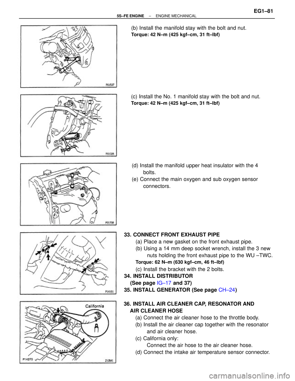
33. CONNECT FRONT EXHAUST PIPE
(a) Place a new gasket on the front exhaust pipe.
(b) Using a 14 mm deep socket wrench, install the 3 new
nuts holding the front exhaust pipe to the WU ±TWC.
Torque: 62 N±m (630 kgf±cm, 46 ft±lbf)
(c) Install the bracket with the 2 bolts.
34. INSTALL DISTRIBUTOR
(See page IG±17 and 37)
35. INSTALL GENERATOR (See page CH±24)
36. INSTALL AIR CLEANER CAP, RESONATOR AND
AIR CLEANER HOSE
(a) Connect the air cleaner hose to the throttle body.
(b) Install the air cleaner cap together with the resonator
and air cleaner hose.
(c) California only:
Connect the air hose to the air cleaner hose.
(d) Connect the intake air temperature sensor connector. (d) Install the manifold upper heat insulator with the 4
bolts.
(e) Connect the main oxygen and sub oxygen sensor
connectors. (c) Install the No. 1 manifold stay with the bolt and nut.
Torque: 42 N±m (425 kgf±cm, 31 ft±lbf)
(b) Install the manifold stay with the bolt and nut.
Torque: 42 N±m (425 kgf±cm, 31 ft±lbf)
± 5S±FE ENGINEENGINE MECHANICALEG1±81
Page 149 of 4770
(e) Clean the crank pin and bearing.
(f) Check the crank pin and bearing for pitting and scrat±
ches.
If the crank pin or bearing is damaged, replace the
bearings. If necessary, grind or replace the crankshaft.
(h) Install the connecting rod cap.
(See step 6 on pages EG1±122)
1st
Torque: 25 N±m (250 kgf±cm, 18 ft±lbf)
2nd Turn 905
NOTICE: Do not turn the crankshaft.
(d) Cover the connecting rod bolts with a short piece of
hose to protect the crankshaft from damage.
(i) Remove the connecting rod cap.
(See procedure (b) and (c) on the previous page) (g) Lay a strip of Plastigage across the crank pin.
± 5S±FE ENGINEENGINE MECHANICALEG1±99
Page 152 of 4770
(d) Clean each main journal and bearing.
(e) Check each main journal and bearing for pitting and
scratches.
If the journal or bearing is damaged, replace the bear±
ings. If necessary, grind or replace the crankshaft. (c) Lift out the crankshaft.
HINT: Keep the upper bearing and upper thrust wash±
ers together with the cylinder block.
(h) Install the main bearing caps.
(See step 4 on page EG1±121)
Torque: 59 N±m (600 kgf±cm, 43 ft±lbf)
NOTICE: Do not turn the crankshaft.
(i) Remove the main bearing caps.
(See procedure (a) and (b) on the previous page) (f) Place the crankshaft on the cylinder block.
(g) Lay a strip of Plastigage across each journal.
± 5S±FE ENGINEENGINE MECHANICALEG1±102
Page 171 of 4770

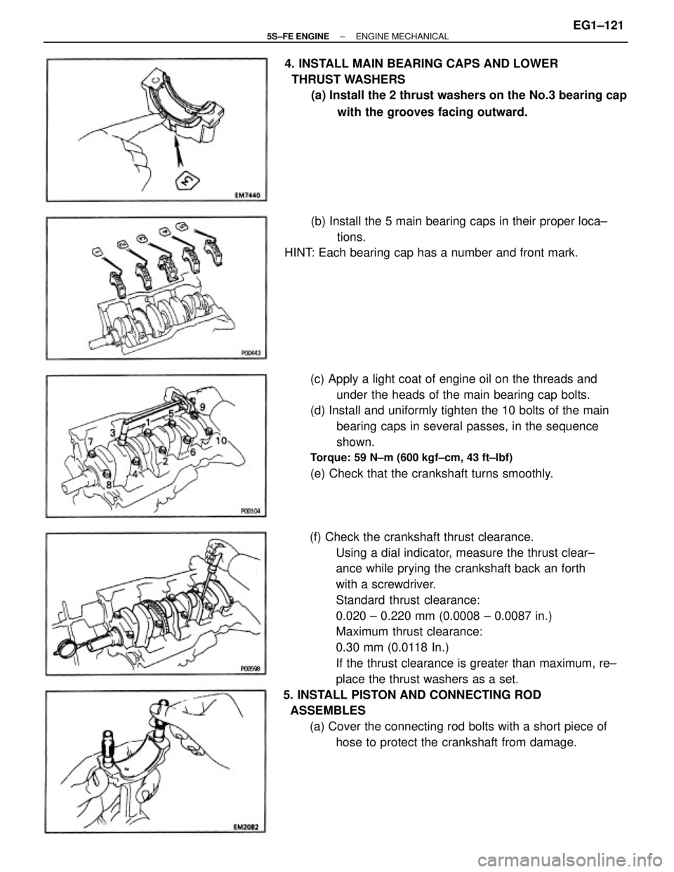
(f) Check the crankshaft thrust clearance.
Using a dial indicator, measure the thrust clear±
ance while prying the crankshaft back an forth
with a screwdriver.
Standard thrust clearance:
0.020 ± 0.220 mm (0.0008 ± 0.0087 in.)
Maximum thrust clearance:
0.30 mm (0.0118 In.)
If the thrust clearance is greater than maximum, re±
place the thrust washers as a set.
5. INSTALL PISTON AND CONNECTING ROD
ASSEMBLES
(a) Cover the connecting rod bolts with a short piece of
hose to protect the crankshaft from damage. (c) Apply a light coat of engine oil on the threads and
under the heads of the main bearing cap bolts.
(d) Install and uniformly tighten the 10 bolts of the main
bearing caps in several passes, in the sequence
shown.
Torque: 59 N±m (600 kgf±cm, 43 ft±lbf)
(e) Check that the crankshaft turns smoothly. 4. INSTALL MAIN BEARING CAPS AND LOWER
THRUST WASHERS
(a) Install the 2 thrust washers on the No.3 bearing cap
with the grooves facing outward.
(b) Install the 5 main bearing caps in their proper loca±
tions.
HINT: Each bearing cap has a number and front mark.
± 5S±FE ENGINEENGINE MECHANICALEG1±121
Page 172 of 4770

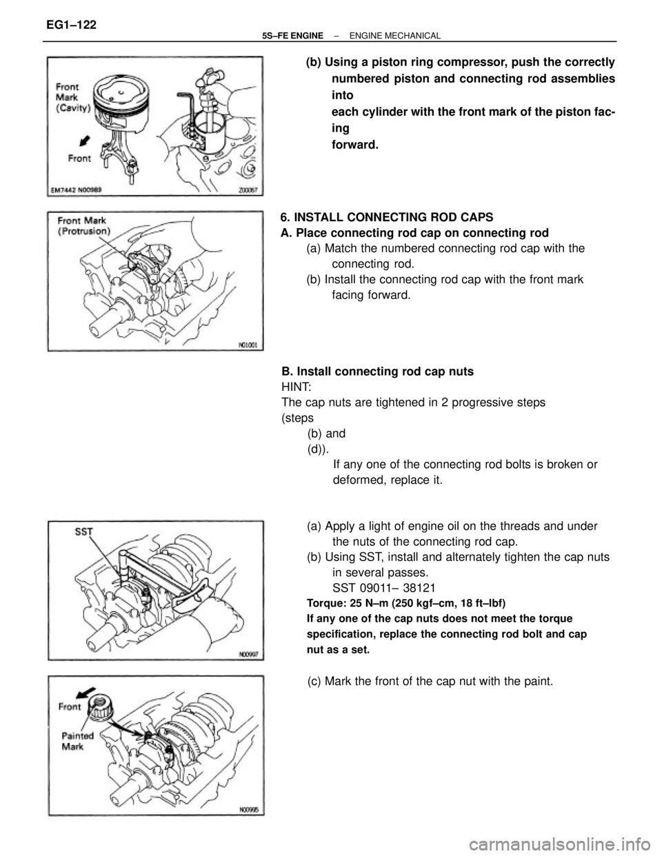
(a) Apply a light of engine oil on the threads and under
the nuts of the connecting rod cap.
(b) Using SST, install and alternately tighten the cap nuts
in several passes.
SST 09011± 38121
Torque: 25 N±m (250 kgf±cm, 18 ft±lbf)
If any one of the cap nuts does not meet the torque
specification, replace the connecting rod bolt and cap
nut as a set.
B. Install connecting rod cap nuts
HINT:
The cap nuts are tightened in 2 progressive steps
(steps
(b) and
(d)).
If any one of the connecting rod bolts is broken or
deformed, replace it. 6. INSTALL CONNECTING ROD CAPS
A. Place connecting rod cap on connecting rod
(a) Match the numbered connecting rod cap with the
connecting rod.
(b) Install the connecting rod cap with the front mark
facing forward. (b) Using a piston ring compressor, push the correctly
numbered piston and connecting rod assemblies
into
each cylinder with the front mark of the piston fac-
ing
forward.
(c) Mark the front of the cap nut with the paint.
± 5S±FE ENGINEENGINE MECHANICALEG1±122
Page 174 of 4770
(h) Recheck that the punch marks of the balance shafts
are aligned with the grooves of No.2 housing.
8. CHECK AND ADJUST BACKLASH OF
CRANKSHAFT GEAR AND NO.1 BALANCE SHAFT
GEAR (See page EG1±94) (c) Wipe clean the installation surface of the spacer.
(d) Place the spacers on the cylinder block.
HINT: When replacing the crankshaft and/or balance
shaft, use the thickest spacers.
(e) Place the engine balancer on the cylinder block.
(f) Check that punch marks shown in the illustration of
the balance shafts are align with the grooves of the
No.2 housing.
(g) While pulling the center part of the engine balancer
in the direction of the arrow, uniformly tighten the
6
bolts in several passes, in the sequence shown.
Torque: 49 N±m (500 kgf±cm, 36 ft±lbf)
9. INSTALL REAR OIL SEAL RETAINER
Install a new gasket and the retainer with the 6 bolts.
Torque: 9.3 N±m (95 kgf±cm, 82 in.±lbf)
± 5S±FE ENGINEENGINE MECHANICALEG1±124