Page 579 of 4770

104BODY ELECTRICALÐAIR CONDITIONING
3. Defroster Nozzle
The front defroster nozzle inner wall is modified into a radial configuration for a smoother air flow and improved
defroster performance.
4. Air Conditioning Amplifier
On the new Camry, the air conditioning amplifier that is provided on the 1MZ±FE engine model is an individual
amplifier unit type and on the 5S±FE engine model is a type that is integrated with the ECM.
The air conditioning amplifier controls the air conditioning system in accordance with the signals received from
sensors, switches, etc.
Function
Details
Magnetic Clutch Relay Control
�When the blower switch and the air conditioning switch are turned on to-
gether, or when the air outlet mode is switched to defroster, the magnetic
clutch relay turns on and activates the compressor.
�When one of the following conditions is met while the compressor is
turned on, the magnetic clutch relay is turned off and stops the compres-
sor:
i) The air temperature immediately after passing through the evaporator
is detected to be below 3�C (37.4�F) by the thermistor.
ii) The compressor speed detected by the lock sensor is compared with
the engine speed signal, and the compressor's slip rate exceeds a pre-
determined level (compressor locked).
iii) ªAir conditioner cutº was requested by the ECM to maintain engine
performance or idling speed.
Compressor Delay ControlWhen the air conditioning switch is turned on, the engagement of the mag-
netic clutch is delayed.
Air Conditioning Indicator Light
Control
�When the blower switch and the air conditioning switch are turned on to-
gether, or when the air outlet mode is switched to defroster, and the com-
pressor is activated, the indicator lamp of the air conditioning switch is
turned on.
�If compressure lock occurs during compressor operation, the indicator
lamp flashes every 1 second.
Page 720 of 4770

CAMRY ± NEW FEATURES
No.2 INJECTOR
SENSORS ACTUATORS
VG
RSO IGF NE
ECM
IGTI�
IGT3
#10
G22
THW
THA
VTA1
STA
SPD
AFR
AFL
OXS
EGLS
THG
KNKR
CF
NSW
A/C
ACIS
FC
ACT
MAFR
HAFL
HREL
#20
#30
#40
#50
#60
MASS AIR FLOW METER
R, 2, L KNKLIGSW
RSC
CRANKSHAFT POSITION SENSOR
�Engine Speed Signal
�Crankshaft Angle Signal
CAMSHAFT POSITION SENSOR
�Crankshaft Angle Signal
ENGINE COOLANT TEMP.
SENSOR
INTAKE AIR TEMP. SENSOR
THROTTLE POSITION SENSOR
�Throttle Position Signal
IGNITION SWITCH
�Starting Signal
�Ignition Signal
VEHICLE SPEED SENSOR
COMBINATION METER
AIR-FUEL RATIO SENSOR
(Bank 1, Sensor 1)
AIR-FUEL RATIO SENSOR
(Bank 2, Sensor 1)
HEATED OXYGEN SENSOR
(Bank 1, Sensor 2)
EGR VALVE POSITION SENSOR
EGR GAS TEMP. SENSOR
KNOCK SENSORS
PARK / NEUTRAL POSITION
SWITCH
�Neutral Start Signal
AIR CONDITIONING AMPLIFIER
�A / C Switch Signal
COOLING FAN RELAYNo.1 INJECTOR
No.3 INJECTOR
No.4 INJECTOR
No.5 INJECTOR
No.6 INJECTOR
ESA
IGNITER
IGNITION COILS
SPARK PLUGS
IAC
CONTROL VALVE
ACIS
VSV
FUEL PUMP CONTROL
CIRCUIT OPENING RELAY
AIR CONDITIONING CONTROL
AIR CONDITIONING
AMPLIFIER
AIR FUEL RATIO SENSOR
HEATER CONTROL
AIR FUEL RATIO SENSOR
HEATER RELAY
AIR FUEL RATIO SENSOR
HEATER (Bank 1, Sensor 1)
AIR FUEL RATIO SENSOR
HEATER (Bank 1, Sensor 2)SFI
(Continued)
KNOCK SENSORS
11
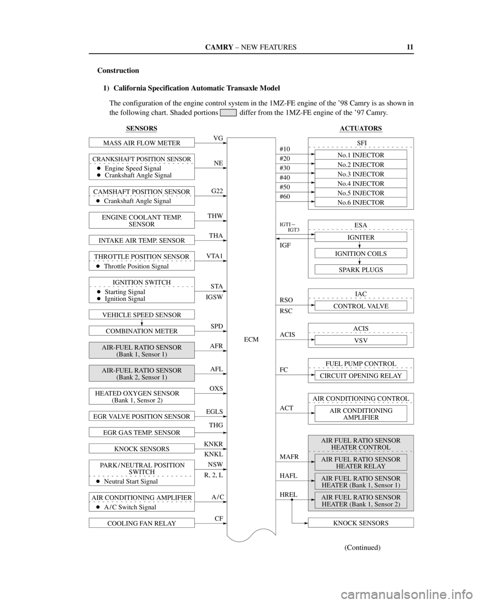
Construction
1) California Specification Automatic Transaxle Model
The configuration of the engine control system in the 1MZ-FE engine of the '98 Camry is as shown in
the following chart. Shaded portions
differ from the 1MZ-FE engine of the '97 Camry.
Page 721 of 4770
CAMRY ± NEW FEATURES
BATT
BATTERY
PS
IMLD
EGR
EVP1
TPC
W
ELS
STP
PTNK
TRC
TXCT
KSW
TC
SIL
EFI MAIN RELAY
+B
EFI ELS2 POWER STEERING OIL
PRESSURE SWITCH
TAILLIGHT & REAR WINDOW
DEFOGGER
STOP LIGHT SWITCH
VAPOR PRESSURE SENSOR
ABS & TRAC ECU*
1
TRANSPONDER KEY
AMPLIFIER*2
UNLOCK WARNING SWITCH*2
DATALINK CONNECTOR 1
DATALINK CONNECTOR 3EGR CONTROL
VSV
EVAP CONTROL
VSV
VAPOR PRESSURE CONTROL
VSV
THEFT DETERRENT INDICATOR
LIGHT*2
MALFUNCTION INDICATOR
LAMP
HTSOXYGEN SENSOR HEATER
CONTROL
HEATED OXYGEN SENSOR
HEATER (Bank 1, Sensor 2)
RXCK
CODE
12
*1: Applicable only to vehicles equipped with the TRAC System.
*
2: Applicable only to vehicles equipped with the Engine Immobiliser System.
Page 722 of 4770
CAMRY ± NEW FEATURES
150EG01
Circuit Opening RelayIgnition
SwitchEFI
Main
Relay
DLC1 Pressure
RegulatorVehicle Speed
SensorPark / Neutral Position Switch*
Fuel Pump
BatteryMIL
Air
Conditioning
Amplifier
DLC3
Stop Light Switch
Electrical Load Switch
Air-Fuel Ratio Sensor Heater Relay
ECM Fuel
Filter
Pulsation
DamperVSV
(for EVAP)Vapor
Pressure
Sensor
VSV
for Vapor
Pressure
Sensor
Charcoal CanisterVCV
Intake Air Temp.
SensorIAC Valve
VSV (for EGR)
Mass Air Flow
Meter
Air-Fuel Ratio Sensor
(Bank 1, Sensor 1)Throttle
Position
Sensor
Actuator
DIS
Injector
VSV (for ACIS)
EGR
Valve
Position
Sensor
EGR
Valve EGR Gas
Temp. Sensor Camshaft
Position
Sensor
Engine Coolant
Temp. SensorWU-TWC
WU-TWC
Crankshaft
Position SensorKnock Sensors
Air-Fuel Ratio Sensor
(Bank 2, Sensor 1)Heated Oxygen Sensor
(Bank 1, Sensor 2)
13
Engine Control System Diagram
1) California Specification Automatic Transaxle Model
*: Only for the Automatic Transaxle Models
Page 733 of 4770

CAMRY ± NEW FEATURES
150NF118
BatteryIgnition Switch
EFI
Relay
Transponder
Key Coil
Transponder
Key AmplifierECMBody
ECU
DLC1
150NF119
Transponder Chip
24
3. Wiring Diagram
4. Construction
The engine immobiliser system consists of the transponder key (ignition key), transponder key coil, trans-
ponder key amplifier, and ECM.
Transponder Key (Ignition Key)
A transponder chip is embedded in the grip of the
ignition key. Each transponder chip contains an
individual transponder key-code (ID code). The
key does not need an internal battery to transmit
a key code.
Transponder Key Coil and Transponder Key Amplifier
The transponder key coil is a ring-shaped coil installed around the ignition key cylinder. The transponder
key amplifier is installed in the back of the key cylinder.
An electrical power circuit to provide power to the transponder key coil has been enclosed in the amplifier.
ECM
The control circuit of the engine immobiliser system has been integrated inside the ECM. As a result, the
time has been reduced taken for the engine to start in case of mismatching key code thus improving the
system's theft deterrent performance.
A maximum of 10 different transponder key codes (master key: 7 types, sub key: 3 types) can be registered
in the ECM.
Page 971 of 4770

'99camry U
175 �
A safety chain must always be used
between the towing vehicle and the
trailer. Leave sufficient slack in the
chain for turns. The chain should
cross under the trailer tongue to
prevent the tongue from dropping to
the ground in case it becomes dam-
aged or separated. For correct safety
chain procedures, follow the hitch or
trailer manufacturer 's recommenda-
tions.
CAUTION
�If the total trailer weight exceeds
453 kg (1000 lb.), trailer brakes are
required.
�Never tap into your vehicle's hy-
draulic system as it would lower its
braking effectiveness.
�Never tow a trailer without using a
safety chain securely attached to
both the trailer and the vehicle. If
damage occurs to the coupling unit
or hitch ball, there is danger of the
trailer wandering over into another
lane.
TIRES
�Ensure that your vehicle's tires are
properly inflated. Adjust the tire pres-
sure to the recommended cold tire
pressure indicated below (see Chapter
7±2 for instructions.):
Tire pressure, kPa (kgf/cm
2 or bar, psi)
5S±FE engine
Front 210 (2.1, 30)
Rear 210 (2.1, 30)
1MZ±FE engine
Front 220 (2.2, 32)
Rear 220 (2.2, 32)
�The trailer tires should be inflated to
the pressure recommended by the trail-
er manufacturer in respect to the total
trailer weight.TRAILER LIGHTS
�Trailer lights must comply with federal,
state/provincial and local regulations.
See your local recreational vehicle
dealer or rental agency for the correct
type of wiring and relays for your trail-
er. Check for correct operation of the
turn signals and stop lights each time
you hitch up. Direct splicing may dam-
age your vehicle's electrical system
and cause a malfunction of your lights.
BREAK±IN SCHEDULE
�Toyota recommends that you do not
tow a trailer with a new vehicle or a
vehicle with any new power train com-
ponent (engine, transmission, differen-
tial, wheel bearing, etc.) for the first
800 km (500 miles) of driving.
MAINTENANCE
�If you tow a trailer, your vehicle will
require more frequent maintenance due
to the additional load. For this informa-
tion, please refer to the scheduled
maintenance information in the ºSched-
uled Maintenance Guideº or ºOwner 's
Manual Supplementº.
�Retighten all fixing bolts of the towing
ball and bracket after approximately
1000 km (600 miles) of trailer driving.
Page 1084 of 4770
NF
NEW FEATURES Ð 5S-FNE ENGINE
TE1
BATT +B
BATTERYEFI MAIN RELAYFC
THCNG 1
PCNG 1VCNG 2
SIL
ECM
THCNG 2
PCNG 2VCNG 3
+B1
21
FUEL TEMP. SENSOR for
FUEL TANK
FUEL TEMP. SENSOR for
DELIVERY PIPE
FUEL PRESSURE SENSOR for
FUEL PIPE
FUEL PRESSURE SENSOR for
DELIVERY PIPE
DATA LINK CONNECTOR 1
FUEL CUT-OFF CONTROL
CIRCUIT OPENING RELAY
FUEL SHUTOFF VALVE for
FUEL TANK
FUEL SHUTOFF VALVE
for FUEL PRESSURE
REGULATOR
FUEL SHUTOFF VALVE for
DELIVERY PIPE
DATA LINK CONNECTOR 3
Page 1151 of 4770

A INTRODUCTION
This manual consists of the following 12 sections:
No.
SectionDescription
A
INDEXIndex of the contents of this manual.
A
INTRODUCTIONBrief explanation of each section.
BHOW TO USE THIS
MANUALInstructions on how to use this manual.
CTROUBLE±
SHOOTINGDescribes the basic inspection procedures for electrical circuits.
DABBREVIATIONSDefines the abbreviations used in this manual.
E
GLOSSARY OF
TERMS AND
SYMBOLS
Defines the symbols and functions of major parts.
FRELAY LOCATIONSShows position of the Electronic Control Unit, Relays, Relay Block, etc.
This section is closely related to the system circuit.
GELECTRICAL
WIRING ROUTINGDescribes position of Parts Connectors, Splice points, Ground points, etc.
This section is closely related to the system circuit.
INDEXIndex of the system circuits.
H
SYSTEM CIRCUITS
Electrical circuits of each system are shown from the power supply through ground
points. Wiring connections and their positions are shown and classified by code
according to the connection method. (Refer to the section, ºHow to use this manualº).
The ºSystem Outlineº and ºService Hintsº useful for troubleshooting are also contained
in this section.
IGROUND POINTSShows ground positions of all parts described in this manual.
J
OVERALL
ELECTRICAL
WIRING DIAGRAM
Provides circuit diagrams showing the circuit connections.
KPOWER SOURCE
(Current Flow Chart)Describes power distribution from the power supply to various electrical loads.
LPART NUMBER OF
CONNECTORSIndicates the part number of the connectors used in this manual.