Page 4425 of 4770

Toyota Supports ASE CertificationPage 1 of 1
AX004±99Title:
TOYOTA DINGHY" TOWING GUIDE
Models:
All Models
Technical Service
BULLETIN
March 19, 1999
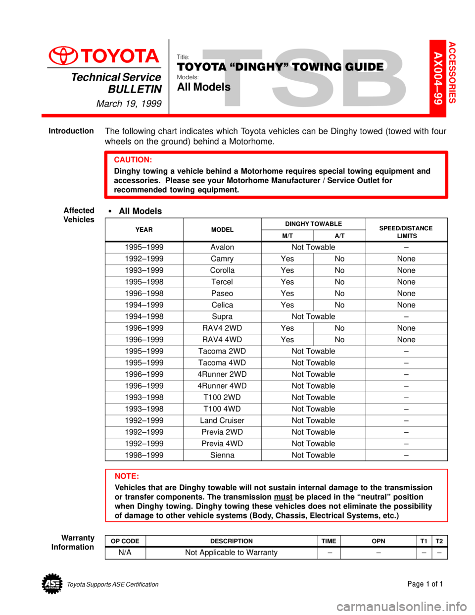
The following chart indicates which Toyota vehicles can be Dinghy towed (towed with four
wheels on the ground) behind a Motorhome.
CAUTION:
Dinghy towing a vehicle behind a Motorhome requires special towing equipment and
accessories. Please see your Motorhome Manufacturer / Service Outlet for
recommended towing equipment.
�All Models
YEARMODELDINGHY TOWABLESPEED/DISTANCEYEARMODELM/TA/TSPEED/DISTANCE
LIMITS
1995±1999AvalonNot Towable±
1992±1999CamryYesNoNone
1993±1999CorollaYesNoNone
1995±1998TercelYesNoNone
1996±1998PaseoYesNoNone
1994±1999CelicaYesNoNone
1994±1998SupraNot Towable±
1996±1999RAV4 2WDYesNoNone
1996±1999RAV4 4WDYesNoNone
1995±1999Tacoma 2WDNot Towable±
1995±1999Tacoma 4WDNot Towable±
1996±19994Runner 2WDNot Towable±
1996±19994Runner 4WDNot Towable±
1993±1998T100 2WDNot Towable±
1993±1998T100 4WDNot Towable±
1992±1999Land CruiserNot Towable±
1992±1999Previa 2WDNot Towable±
1992±1999Previa 4WDNot Towable±
1998±1999SiennaNot Towable±
NOTE:
Vehicles that are Dinghy towable will not sustain internal damage to the transmission
or transfer components. The transmission must
be placed in the ªneutralº position
when Dinghy towing. Dinghy towing these vehicles does not eliminate the possibility
of damage to other vehicle systems (Body, Chassis, Electrical Systems, etc.)
OP CODEDESCRIPTIONTIMEOPNT1T2
N/ANot Applicable to Warranty ±±±±
ACCESSORIES
Introduction
Affected
Vehicles
Warranty
Information
Page 4435 of 4770

Toyota Supports ASE CertificationPage 1 of 1
AX007±00Title:
INTERCHANGEABILITY OF ACCESSORY
ALLOY WHEELS
Models:
'99 ± '01 Avalon, Camry, Solara & Sienna
Technical Service
BULLETIN
September 22, 2000
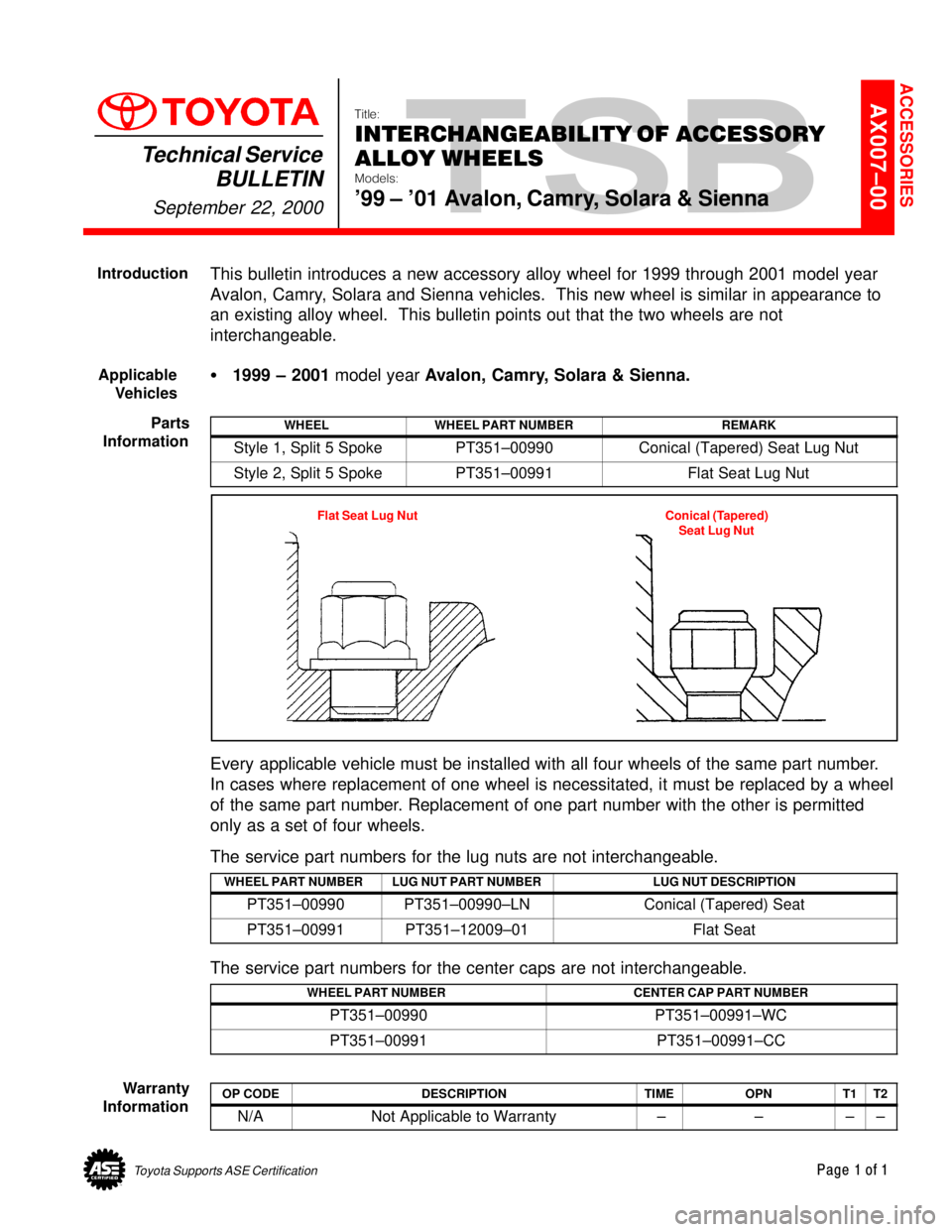
This bulletin introduces a new accessory alloy wheel for 1999 through 2001 model year
Avalon, Camry, Solara and Sienna vehicles. This new wheel is similar in appearance to
an existing alloy wheel. This bulletin points out that the two wheels are not
interchangeable.
�1999 ± 2001 model year Avalon, Camry, Solara & Sienna.
WHEELWHEEL PART NUMBERREMARK
Style 1, Split 5 SpokePT351±00990Conical (Tapered) Seat Lug Nut
Style 2, Split 5 SpokePT351±00991Flat Seat Lug Nut
Flat Seat Lug Nut Conical (Tapered)
Seat Lug Nut
Every applicable vehicle must be installed with all four wheels of the same part number.
In cases where replacement of one wheel is necessitated, it must be replaced by a wheel
of the same part number. Replacement of one part number with the other is permitted
only as a set of four wheels.
The service part numbers for the lug nuts are not interchangeable.
WHEEL PART NUMBERLUG NUT PART NUMBERLUG NUT DESCRIPTION
PT351±00990PT351±00990±LNConical (Tapered) Seat
PT351±00991PT351±12009±01Flat Seat
The service part numbers for the center caps are not interchangeable.
WHEEL PART NUMBERCENTER CAP PART NUMBER
PT351±00990PT351±00991±WC
PT351±00991PT351±00991±CC
OP CODEDESCRIPTIONTIMEOPNT1T2
N/ANot Applicable to Warranty ±±±±
ACCESSORIES
Introduction
Applicable
Vehicles
Parts
Information
Warranty
Information
Page 4515 of 4770
BRAKE DISC ANTI±RUST COVER REMOVAL (CONT'D)Page 2 of 2
RECOMMENDED REMOVAL PROCEDURE:
Turn the right front wheel to full right lock.
Unhook the Anti±Rust Cover from the disc brake dust cover, then pull the center of the Anti±Rust
Cover toward the wheel. This separates the Anti±Rust Cover from the disc brake dust cover (see
illustration below).
Pull the center of the Anti±Rust Cover by hand towards you to break the thin portion of cover.
Remove the Anti±Rust Cover along the arch of the wheel disc by shaking it up and down. If the
cover is torn while removing, check to see that no parts of the cover are left inside.
Turn the steering wheel to full left lock and perform the same steps on the left front wheel. If
applicable, also remove the Anti±Rust Covers on the rear brakes.
Indicate on the new car inspection sheet that the Anti±Rust Covers have been removed.
Page 4517 of 4770
TOYOTA MOTOR SALES U.S.A., INC.
This TSB outlines the causes of brake vibration and pulsation, as well as the best corrective
measures to use.
CONTENTS
1) Symptoms of brake vibration and pulsation
2) Cause of vibration/pulsation problems
3) Advantages of using an on±car brake lathe
4) Rotor replacement and off±car brake lathe procedure
1) SYMPTOMS OF BRAKE VIBRATION AND PULSATION
Brake vibration problems generally involve one or both of two phenomena: body vibration and/
or pedal pulsation.
A. BRAKE VIBRATION
Applying brakes causes vibration to occur in the instrument panel, steering column, steering
wheel, and/or body of the vehicle (See Figure 1 below).
BRAKE VIBRATION AND/OR PULSATIONPage 1 of 6
BRAKES
BR94±002
FEBRUARY 7, 1994
ALL MODELS
Figure 1
Page 4518 of 4770
BR002±94
BRAKE VIBRATION AND/OR PULSATIONPage 2 of 6
B. PEDAL PULSATION
Applying brakes causes the brake pedal to pulsate. This brake pulsation sometimes
causes the steering wheel to oscillate when the brakes are applied (See Figure 2 below).
2) CAUSE OF VIBRATION/PULSATION PROBLEMS
Brake rotor thickness variation causes brake vibration due to changes in the braking force as
thick/thin portions of the rotor pass the pads. Brake rotor thickness variation can be measured
with a micrometer as shown in Figure 3 below.
Figure 2
10 mm
Divide Into
8 Equal Parts & Measure
at each location
Thickness Variation = Maximum ± Minimum
Figure 3
Page 4521 of 4770
BR002±94
BRAKE VIBRATION AND/OR PULSATIONPage 5 of 6
B. Installation of Rotor
± Check wheel bearing pre±load. If excessive movement is found, adjust bearing
pre±load.
± Using a dial indicator, measure the rotor 10 mm from the outside edge
(See Figure 5 below).
Figure 5
Page 4522 of 4770
BR002±94
BRAKE VIBRATION AND/OR PULSATIONPage 6 of 6
C. Phase Match Rotor To Hub
± If rotor runout is at the maximum value or greater, (refer to appropriate repair manual)
index the rotor one lug and measure the runout again. Repeat this process, moving the
rotor one lug each time, until the position is found where the runout is at the minimum and
within the maximum value listed in the appropriate repair manual
(See Figure 6 below).
± Tighten lug nuts to the specified torque following a star sequence when installing wheel
(See Figure 7 below).
Note: DO NOT USE AIR IMPACT WRENCH.
Four Holes Five Holes
Figure 7Figure 6
Page 4525 of 4770

BRAKE PAD CLICKING NOISE ± BR004±00 October 20, 2000
Page 2 of 4
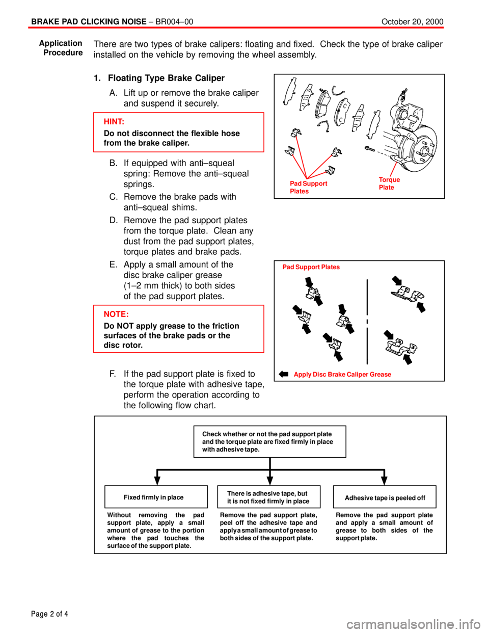
There are two types of brake calipers: floating and fixed. Check the type of brake caliper
installed on the vehicle by removing the wheel assembly.
1. Floating Type Brake Caliper
A. Lift up or remove the brake caliper
and suspend it securely.
HINT:
Do not disconnect the flexible hose
from the brake caliper.
B. If equipped with anti±squeal
spring: Remove the anti±squeal
springs.
C. Remove the brake pads with
anti±squeal shims.
D. Remove the pad support plates
from the torque plate. Clean any
dust from the pad support plates,
torque plates and brake pads.
E. Apply a small amount of the
disc brake caliper grease
(1±2 mm thick) to both sides
of the pad support plates.
NOTE:
Do NOT apply grease to the friction
surfaces of the brake pads or the
disc rotor.
F. If the pad support plate is fixed to
the torque plate with adhesive tape,
perform the operation according to
the following flow chart.
Without removing the pad
support plate, apply a small
amount of grease to the portion
where the pad touches the
surface of the support plate.Fixed firmly in placeThere is adhesive tape, but
it is not fixed firmly in placeAdhesive tape is peeled offRemove the pad support plate,
peel off the adhesive tape and
apply a small amount of grease to
both sides of the support plate.Remove the pad support plate
and apply a small amount of
grease to both sides of the
support plate.
Check whether or not the pad support plate
and the torque plate are fixed firmly in place
with adhesive tape.
Application
Procedure
Pad Support
PlatesTorque
Plate
Apply Disc Brake Caliper Grease
Pad Support Plates