Page 4526 of 4770
BRAKE PAD CLICKING NOISE ± BR004±00 October 20, 2000
Page 3 of 4
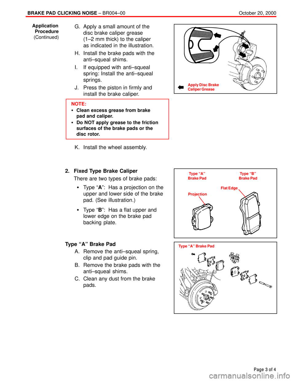
G. Apply a small amount of the
disc brake caliper grease
(1±2 mm thick) to the caliper
as indicated in the illustration.
H. Install the brake pads with the
anti±squeal shims.
I. If equipped with anti±squeal
spring: Install the anti±squeal
springs.
J. Press the piston in firmly and
install the brake caliper.
NOTE:
�Clean excess grease from brake
pad and caliper.
�Do NOT apply grease to the friction
surfaces of the brake pads or the
disc rotor.
K. Install the wheel assembly.
2. Fixed Type Brake Caliper
There are two types of brake pads:
�Type ªAº: Has a projection on the
upper and lower side of the brake
pad. (See illustration.)
�Type ªBº: Has a flat upper and
lower edge on the brake pad
backing plate.
Type ªAº Brake Pad
A. Remove the anti±squeal spring,
clip and pad guide pin.
B. Remove the brake pads with the
anti±squeal shims.
C. Clean any dust from the brake
pads.
Application
Procedure
(Continued)
Apply Disc Brake
Caliper Grease
Type ªAº
Brake PadType ªBº
Brake Pad
ProjectionFlat Edge
Type ªAº Brake Pad
Page 4527 of 4770
BRAKE PAD CLICKING NOISE ± BR004±00 October 20, 2000
Page 4 of 4
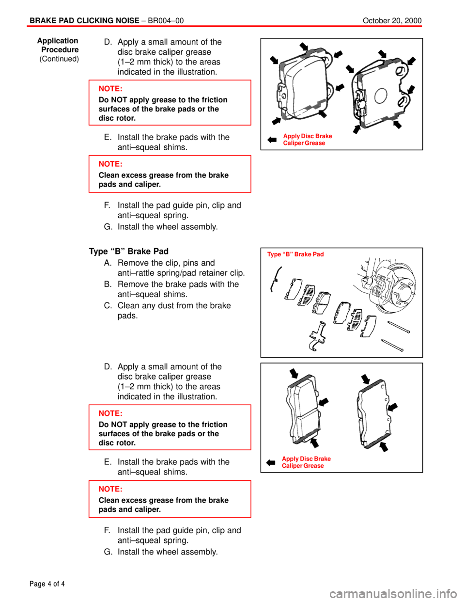
D. Apply a small amount of the
disc brake caliper grease
(1±2 mm thick) to the areas
indicated in the illustration.
NOTE:
Do NOT apply grease to the friction
surfaces of the brake pads or the
disc rotor.
E. Install the brake pads with the
anti±squeal shims.
NOTE:
Clean excess grease from the brake
pads and caliper.
F. Install the pad guide pin, clip and
anti±squeal spring.
G. Install the wheel assembly.
Type ªBº Brake Pad
A. Remove the clip, pins and
anti±rattle spring/pad retainer clip.
B. Remove the brake pads with the
anti±squeal shims.
C. Clean any dust from the brake
pads.
D. Apply a small amount of the
disc brake caliper grease
(1±2 mm thick) to the areas
indicated in the illustration.
NOTE:
Do NOT apply grease to the friction
surfaces of the brake pads or the
disc rotor.
E. Install the brake pads with the
anti±squeal shims.
NOTE:
Clean excess grease from the brake
pads and caliper.
F. Install the pad guide pin, clip and
anti±squeal spring.
G. Install the wheel assembly.
Application
Procedure
(Continued)
Apply Disc Brake
Caliper Grease
Type ªBº Brake Pad
Apply Disc Brake
Caliper Grease
Page 4548 of 4770
READINESS MONITOR DRIVE PATTERNS ± EG003-02 RevisedMarch 29, 2002
Page 17 of 23
Drive Pattern Preconditions
The monitor will not run unless:
�MIL is OFF.
�Fuel level is between 1/2 to 3/4 full (for faster completion)
.
�Altitude is 7800 feet (2400 m) or less.*
�ECT (Coolant Temp) is between 40�F and 95�F (4.4�C ± 35�C).
�IAT (Intake Air) is between 40�F and 95�F (4.4�C ± 35�C).*
�Cold Soak Procedure has been completed.
* For 2002 MY and later vehicles: The readiness test can be completed in cold ambient conditions
(less than 40�F / 4.4�C) and/or at high altitudes (more than 7800 feet / 2400 m) if the complete drive
pattern (including Cold Soak) is repeated a second time after cycling the ignition OFF.
NOTE:
Before starting the engine, the difference between ECT (Coolant Temp) and IAT (Intake
Air) must be less than 13�F (7�C). (Refer to Examples 1 and 2 on previous page.)
Drive Pattern Procedure
�Connect the OBDII Scantool to DLC3 to check monitor status and preconditions.
�Release the pressure in the fuel tank by removing and then reinstalling the fuel tank
cap.
2a. Start the engine and allow it to idle until ECT (Coolant Temp) is 167�F (75�C) or
greater. (See illustration on previous page.)
2b. Race the engine at 3,000 rpm for approximately 10 seconds. (See illustration on
previous page.)
2c. Allow the engine to idle with the A/C ON (to create a slight load) for 15 ± 50
minutes. (See illustration on previous page.)
NOTE:
If the vehicle is not equipped with A/C put a slight load on the engine by doing the
following:
�Securely set the parking brake.
�Block the drive wheels with wheel chocks.
�Allow the vehicle to idle in drive for 15 ± 50 minutes.
NOTE:
The readiness status may not switch to ªcompleteº after the first drive pattern trip if a
Pending Code has been set (first trip for a two±trip DTC).
�Pending Codes are available from the DTC Info Menu in Enhanced OBDII.
�Pending Codes indicate a POTENTIAL problem was detected. A second trip is
needed to confirm the DTC prior to diagnosis.
�Once a second trip is completed, a current DTC will be stored. Readiness
Monitor
Drive
Patterns:
EVAP
Monitors
(Continued)
Page 4645 of 4770

WARRANTY PARTS MARKING PROCEDURE ± PG006-03September 26, 2003
Page 2 of 3
Dealers are requested to mark the location of the failure of all warranty parts that are
listed below.
This list is not inclusive. There may be other components that can be
marked in the area of failure. All other parts that can be marked should be marked.
assist grip assy headlamps
audio (blemish) headliner
back door garnish hoses
bumper covers instrument panel safety pad sub±assy
cargo cover (retractable) Interior light assemblies and covers
carpet knobs, levers, handles
clutch disc l/pulley pump assy
clutch flywheel mirrors (side and rearview)
combination meter glass navigation or VES screens
console and components pillar garnish
cowl assy rack and pinion/power steering gear assy
cowl side trim sub±assy radiator
cupholders room partition board
cylinder head cover sub±assy rotors (mark where min. runout is exceeded or warped)
dash panel insulator assy seat covers/cushions
dashboard and trim seat tracks
disc wheel soft trim
display panels spare tire cover
door handle assy steering column cover
door moulding steering wheel
door trim panel & molding tail lamps and covers
emblems transmission oil pan
engine oil pan visor
exhaust manifold washer jar
floor and cargo mats wheel cap
gear shift knob wheels
grills
Parts
Marking
Requirement
Parts
Marking
List
Page 4658 of 4770
SUSPENSION BALL JOINT INSPECTION ± PG027-02December 4, 2002
Page 6 of 8
NOTE:
�Be sure to check the table for the
applicable inspection type based on
the vehicle model.
�Refer to the table for the standard
free play values.
1. Inspect Lower Ball Joint Free Play
A. Move the hub up and down by
hand (most models with wishbone
suspension):
a. Remove the tire.
b. Install the 2 lug nuts.
c. Inspect the free play while
moving the lug nuts up and
down at a force of 67 lbf
(294 N, 30 kgf).
B. Move the lower arm using a lever
(some models with double
wishbone type suspension):
a. Lift up the vehicle.
b. Place the tip of the lever to the
wheel and inspect the free
play while moving the lower
arm up and down.
C. Move the lower arm by hand (all
models with strut type suspension
and some models with wishbone
type suspension):
a. Lift up the vehicle.
b. Inspect the free play while
moving the lower arm up and
down at a force of 67 lbf
(294 N, 30 kgf).
On±Vehicle
Inspection
Page 4692 of 4770
Toyota Supports ASE CertificationPage 1 of 2
ST001-01Title:
STEERING WHEEL NUT SERVICE
SPECIFICATION
Models:
All Applicable Models
Technical Service
BULLETIN
February 16, 2001
To make the steering wheel installation procedure similar for all models, the steering
wheel nut tightening torque has been standardized.
MODELMODEL YEARS
TERCELEL42, 531991 ± 1998
ECHONCP122000
PASEOEL44, 541992 ± 1997
COROLLAAE10#, ZZE1101993 ± 2001
CELICAAT180, ST18#, AT2#,
ST2#, ZZT23#1990 ± 2000
MR2SW2#, ZZW301991 ± 1995; 2000
CAMRYSXV10, 20, MCV10, 201992 ± 2000
CAMRY CNGSXV232000 ± 2001
CAMRY SOLARASXV20, MCV201999 ± 2000
AVALONMCX10, 201995 ± 2000
SUPRAJZA801993 1/2 ± 1998
RAV4SXA1#1996 ± 2000
RAV4 EVBEA111998 ± 2000
PREVIATRC10, 201991 ± 1997
SIENNAMCL101998 ± 2000
HIGHLANDERACU20, 25, MCU20, 252001
4RUNNERRN12#, 13#, VZN12#, 13#,
18#, RZN180, 1851990 ± 2000
LAND CRUISERFZ80, FZJ80, UZJ1001991 ± 2000
TRUCKRN8#, 9#, 10#, 110,
VZN85, 9#, 10#, 1101989 ± 1995
TACOMARZN140, 150, 161, 171,
19#, VZN150, 160, 170, 1951995 1/2 ± 2000
T100VCK10, 201993 ± 1998
TUNDRAVCK30, 40, UCK30, 402000
OP CODEDESCRIPTIONTIMEOPNT1T2
N/ANot Applicable to Warranty ±±±±
STEERING
Introduction
Applicable
Vehicles
Warranty
Information
Page 4693 of 4770
STEERING WHEEL NUT SERVICE SPECIFICATION ± ST001-01 February 16, 2001
Page 2 of 2
50 N�m (510 kgf�cm, 37 ft�lbf)
35 N�m (360 kgf�cm, 26 ft�lbf)
Steering Wheel
Installation Nut
Steering Wheel
Lower
No. 2 Cover
Steering Wheel
Lower
No. 3 CoverSteering Wheel Pad
Steering Wheel
Steering ColumnService
Information
Page 4694 of 4770
Toyota Supports ASE CertificationPage 1 of 1
ST002±98Title:
STEERING GEAR REMOVAL/
REPLACEMENT
Models:
All Models equipped with SRS Airbag
Technical Service
BULLETIN
May 22, 1998
The following information is provided to supplement the Repair Manual procedure
for
removing/installing the steering gearbox or rack and pinion on vehicles equipped with a
driver 's side Supplemental Restraint System (SRS) Airbag.
CAUTION:
When the intermediate shaft is disconnected and the steering wheel is turned freely,
the SRS spiral cable may be broken.
Therefore, as a precaution, make sure to pass
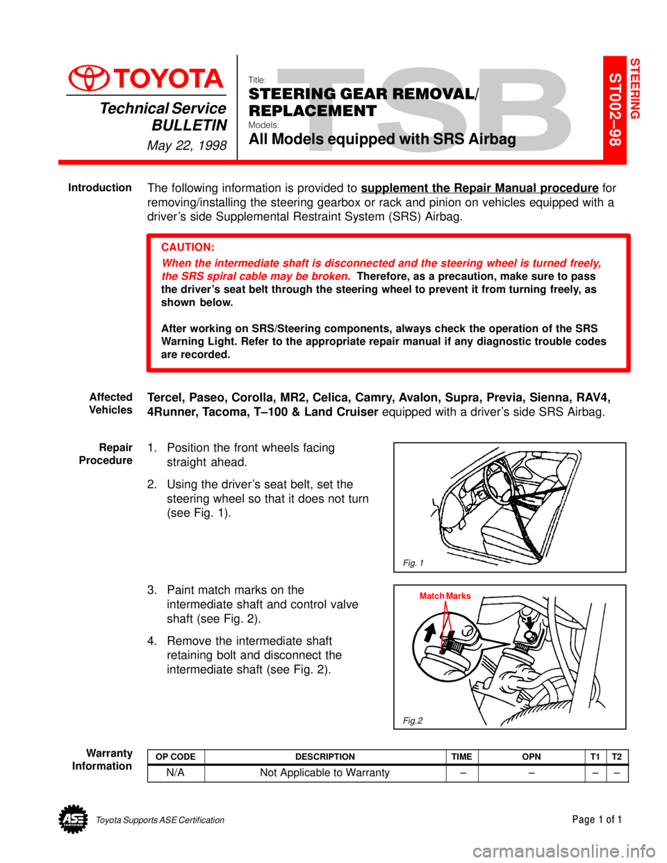
the driver's seat belt through the steering wheel to prevent it from turning freely, as
shown below.
After working on SRS/Steering components, always check the operation of the SRS
Warning Light. Refer to the appropriate repair manual if any diagnostic trouble codes
are recorded.
Tercel, Paseo, Corolla, MR2, Celica, Camry, Avalon, Supra, Previa, Sienna, RAV4,
4Runner, Tacoma, T±100 & Land Cruiser equipped with a driver's side SRS Airbag.
1. Position the front wheels facing
straight ahead.
2. Using the driver's seat belt, set the
steering wheel so that it does not turn
(see Fig. 1).
3. Paint match marks on the
intermediate shaft and control valve
shaft (see Fig. 2).
4. Remove the intermediate shaft
retaining bolt and disconnect the
intermediate shaft (see Fig. 2).
OP CODEDESCRIPTIONTIMEOPNT1T2
N/ANot Applicable to Warranty ±±±±
STEERING
Introduction
Affected
Vehicles
Fig. 1
Repair
Procedure
Match Marks
Fig.2
Warranty
Information