Page 2468 of 4770
DI±48
± DIAGNOSTICSENGINE (5S±FE)
283 Author�: Date�:
2 Check thermostat (See page CO±10).
NG Replace thermostat.
OK
Replace engine coolant temp. sensor.
Page 2471 of 4770
FI7052
A00369
ON
VC (+)
± DIAGNOSTICSENGINE (5S±FE)
DI±51
286 Author�: Date�:
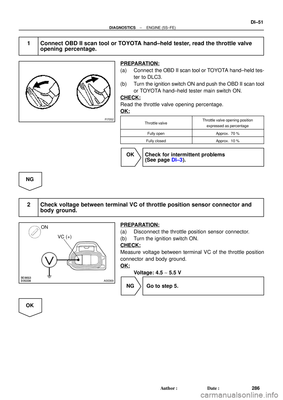
1 Connect OBD II scan tool or TOYOTA hand±held tester, read the throttle valve
opening percentage.
PREPARATION:
(a) Connect the OBD II scan tool or TOYOTA hand±held tes-
ter to DLC3.
(b) Turn the ignition switch ON and push the OBD II scan tool
or TOYOTA hand±held tester main switch ON.
CHECK:
Read the throttle valve opening percentage.
OK:
Throttle valveThrottle valve opening position
expressed as percentage
Fully openApprox. 70 %
Fully closedApprox. 10 %
OK Check for intermittent problems
(See page DI±3).
NG
2 Check voltage between terminal VC of throttle position sensor connector and
body ground.
PREPARATION:
(a) Disconnect the throttle position sensor connector.
(b) Turn the ignition switch ON.
CHECK:
Measure voltage between terminal VC of the throttle position
connector and body ground.
OK:
Voltage: 4.5 ~ 5.5 V
NG Go to step 5.
OK
Page 2472 of 4770
A03013A03413
ON
VTA
(+)E2
(±)
w/o Immobiliser
w/ Immobiliser
VTA
(+)E2
(±)
DI±52
± DIAGNOSTICSENGINE (5S±FE)
287 Author�: Date�:
3 Check throttle position sensor (See page SF±29).
NG Replace throttle position sensor.
OK
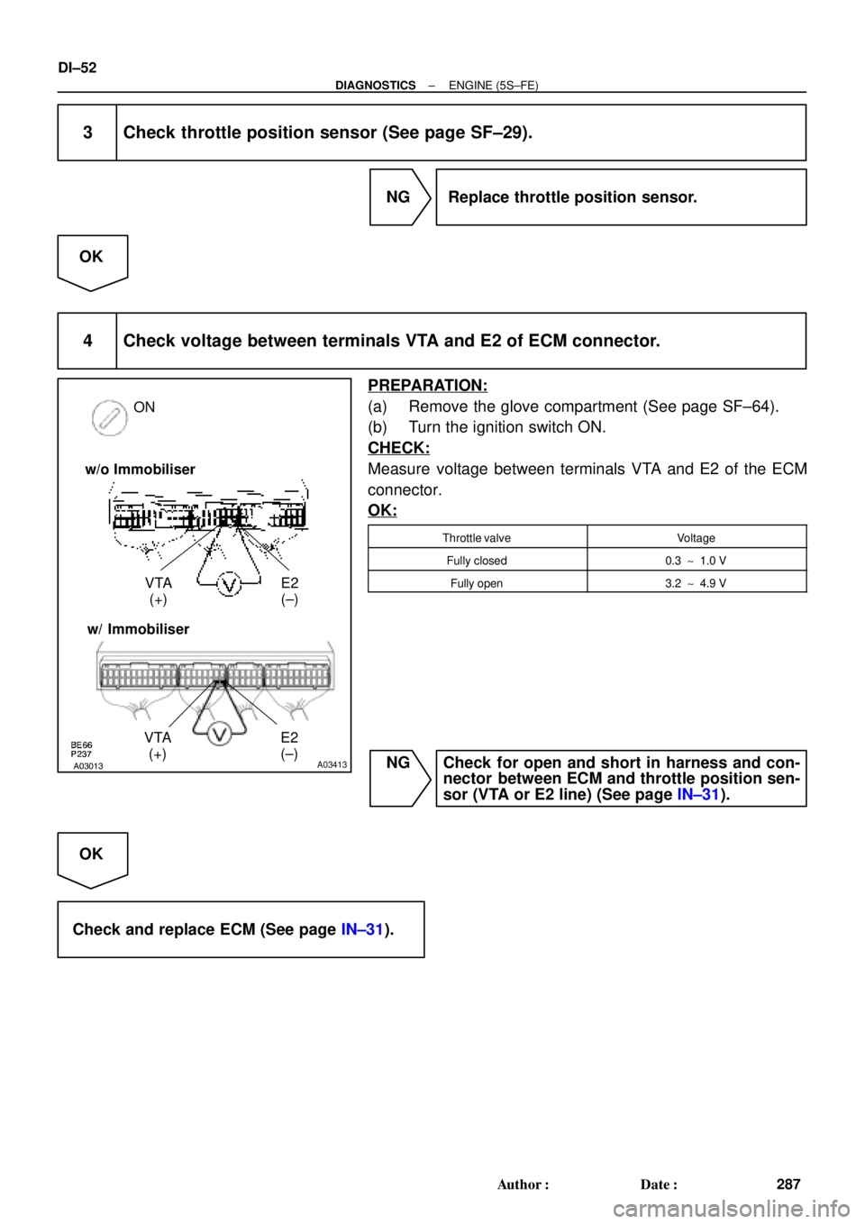
4 Check voltage between terminals VTA and E2 of ECM connector.
PREPARATION:
(a) Remove the glove compartment (See page SF±64).
(b) Turn the ignition switch ON.
CHECK:
Measure voltage between terminals VTA and E2 of the ECM
connector.
OK:
Throttle valveVoltage
Fully closed0.3 ~ 1.0 V
Fully open3.2 ~ 4.9 V
NG Check for open and short in harness and con-
nector between ECM and throttle position sen-
sor (VTA or E2 line) (See page IN±31).
OK
Check and replace ECM (See page IN±31).
Page 2473 of 4770
A03008A03414
ON
VC
(+) E2
(±)
w/o Immobiliser
w/ Immobiliser
VC
(+) E2
(±)
± DIAGNOSTICSENGINE (5S±FE)
DI±53
288 Author�: Date�:
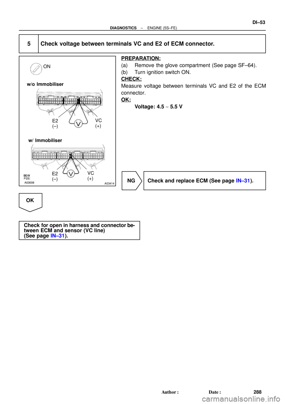
5 Check voltage between terminals VC and E2 of ECM connector.
PREPARATION:
(a) Remove the glove compartment (See page SF±64).
(b) Turn ignition switch ON.
CHECK:
Measure voltage between terminals VC and E2 of the ECM
connector.
OK:
Voltage: 4.5 ~ 5.5 V
NG Check and replace ECM (See page IN±31).
OK
Check for open in harness and connector be-
tween ECM and sensor (VC line)
(See page IN±31).
Page 2477 of 4770

DI±57
292 Author�: Date�:
1 Are there any other codes (besides DTC P0125) being output?
YES Go to relevant DTC chart.
NO
2 Connect OBD II scan tool or TOYOTA hand±held")
± DIAGNOSTICSENGINE (5S±FE)
DI±57
292 Author�: Date�:
1 Are there any other codes (besides DTC P0125) being output?
YES Go to relevant DTC chart.
NO
2 Connect OBD II scan tool or TOYOTA hand±held tester, and read value for volt-
age output of A/F sensor.
PREPARATION:
(a) Connect the OBD II scan tool or TOYOTA hand±held tester to the DLC3.
(b) Warm up the A/F sensor with the engine at 2,500 rpm for approx. 90 sec.
CHECK:
Read voltage value of the A/F sensor on the screen of OBD II scan tool or TOYOTA hand±held tester when
you perform all the following conditions.
HINT:
The voltage of AF� terminal of ECM is 3.3 V fixed and the A/F� terminal is 3.0 V fixed. Therefore, it is impos-
sible to check the A/F sensor output voltage at the terminals (AF�/AF�) of ECM.
OK:
ConditionA/F Sensor Voltage Value
Engine idling
Engine racing� Not remains at 3.30 V (* 0.660 V)
�Not remains at38V(*076V)ormoreDriving at engine speed 1,500 rpm or more and vehicle
speed 40 km/h (25 mph) or more, and operate throttle valve
open and close� Not remains at 3.8 V (* 0.76 V) or more
� Not remains at 2.8 V (* 0.56 V) or less
*: When you use the OBD II scan tool (excluding TOYOTA hand±held tester)
HINT:
�During fuel enrichment, there is a case that the output voltage of the A/F sensor is below 2.8 V (* 0.56
V), it is normal.
�During fuel cut, there is a case that the output voltage of the A/F sensor is above 3.8 V (* 0.76 V), it
is normal.
�If output voltage of the A/F sensor remains at 3.30 V (* 0.660 V) even after performing all the above
conditions, A/F the sensor circuit may be open.
�If output voltage of A/F sensor remains at 3.8 V (* 0.76 V) or more, or 2.8 V (* 0.56 V) or less even after
performing all the above conditions, A/F sensor circuit may be short.
*: When you use the OBD II scan tool (excluding TOYOTA hand±held tester).
OK Go to step 10.
NG
Page 2478 of 4770
DI±58
± DIAGNOSTICSENGINE (5S±FE)
293 Author�: Date�:
3 Check for open and short in harness and connector between ECM and A/F sen-
sor (See page IN±31).
NG Repair or replace harness or connector.
OK
4 Check resistance of A/F sensor heater (See page SF±59).
NG Replace A/F sensor.
OK
5 Check air induction system (See page SF±1).
NG Replace or replace.
OK
6 Check EGR system (See page EC±12).
NG Repair EGR system.
OK
7 Check fuel pressure (See page SF±6).
NG Check and repair fuel pump, fuel pipe line and
filter (See page SF±1).
OK
Page 2479 of 4770
± DIAGNOSTICSENGINE (5S±FE)
DI±59
294 Author�: Date�:
8 Check injector injection (See page SF±23).
NG Replace injector.
OK
9 Check gas leakage on exhaust system.
NG Repair or replace.
OK
Replace A/F sensor.
10 Perform confirmation driving pattern (See page DI±152).
Go
11 Is there DTC P0125 being output again?
YES Check and replace ECM.
NO
Page 2480 of 4770
DI±60
± DIAGNOSTICSENGINE (5S±FE)
295 Author�: Date�:
12 Did vehicle runs out of fuel in the past?
NO Check for intermittent problems.
YES
DTC P0125 is caused by running out of fuel.