Page 2515 of 4770
± DIAGNOSTICSENGINE (5S±FE)
DI±95
330 Author�: Date�:
4 Check resistance of injector of misfiring cylinder (See page SF±20).
NG Replace injector.
OK
Check for open and short in harness and
connector between injector and ECM
(See page IN±31).
5 Check fuel pressure (See page SF±6).
NG Check and repair fuel pump, pressure regula-
tor, fuel pipe line and filter.
OK
6 Check injector injection (See page SF±23).
NG Replace injector.
OK
7 Check EGR system (See page EC±12).
NG Repair EGR system.
OK
Page 2516 of 4770
DI±96
± DIAGNOSTICSENGINE (5S±FE)
331 Author�: Date�:
8 Check manifold absolute pressure sensor and engine coolant temp. sensor
(See pages SF±53 AND SF±49).
NG Repair or replace.
OK
Check compression pressure, valve
clearance and valve timing
(See pages EM±3, EM±4 AND EM±23).
Page 2518 of 4770
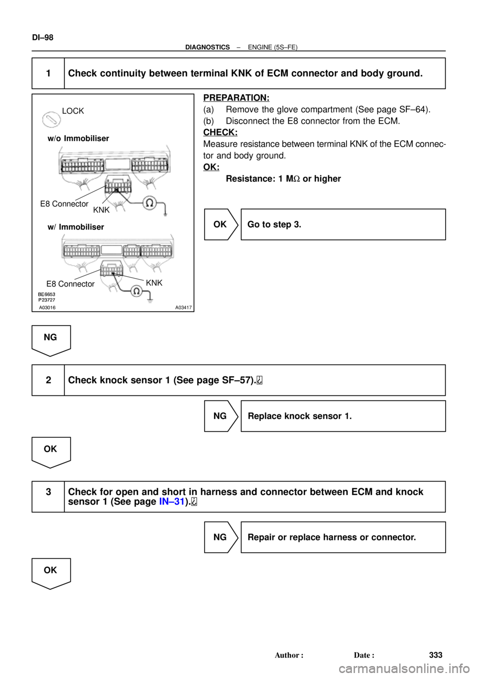
A03016A03417
LOCK
KNK E8 Connector
w/o Immobiliser
w/ Immobiliser
KNK
E8 Connector
DI±98
± DIAGNOSTICSENGINE (5S±FE)
333 Author�: Date�:
1 Check continuity between terminal KNK of ECM connector and body ground.
PREPARATION:
(a) Remove the glove compartment (See page SF±64).
(b) Disconnect the E8 connector from the ECM.
CHECK:
Measure resistance between terminal KNK of the ECM connec-
tor and body ground.
OK:
Resistance: 1 MW or higher
OK Go to step 3.
NG
2 Check knock sensor 1 (See page SF±57).
NG Replace knock sensor 1.
OK
3 Check for open and short in harness and connector between ECM and knock
sensor 1 (See page IN±31).
NG Repair or replace harness or connector.
OK
Page 2519 of 4770
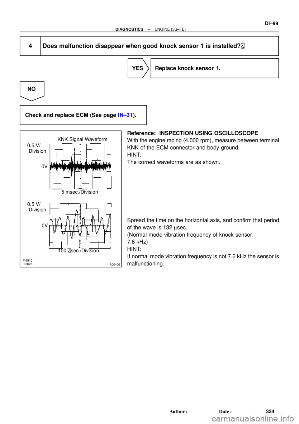
A00406
KNK Signal Waveform
0.5 V/
Division
0V
0V5 msec./Division
100
sec./Division 0.5 V/
Division
± DIAGNOSTICSENGINE (5S±FE)
DI±99
334 Author�: Date�:
4 Does malfunction disappear when good knock sensor 1 is installed?
YES Replace knock sensor 1.
NO
Check and replace ECM (See page IN±31).
Reference: INSPECTION USING OSCILLOSCOPE
With the engine racing (4,000 rpm), measure between terminal
KNK of the ECM connector and body ground.
HINT:
The correct waveforms are as shown.
Spread the time on the horizontal axis, and confirm that period
of the wave is 132 msec.
(Normal mode vibration frequency of knock sensor:
7.6 kHz)
HINT:
If normal mode vibration frequency is not 7.6 kHz the sensor is
malfunctioning.
Page 2521 of 4770

10 msec./Division (Idling)
± DIAGNOSTICSENGINE (5S±FE)
DI±101
336 Author�: D")
A01991A01992A02359
G and NE Signal Waveforms
5 V/
Division
5 V/
Division G
NE
G
NE20 msec./Division (Idling)
10 msec./Division (Idling)
± DIAGNOSTICSENGINE (5S±FE)
DI±101
336 Author�: Date�:
INSPECTION PROCEDURE
HINT:
�Perform troubleshooting of DTC 335 first. If notrouble is found, troubleshoot the following mechanical
system.
�Read freeze frame data using TOYOTA hand±held tester or OBD II scan tool. Because freeze frame
records the engine conditions when the malfunction is detected, when troubleshooting it is useful for
determining whether the vehicle was running or stopped, the engine warmed up or not, the air±fuel
ratio lean or rich, etc. at the time of the malfunction.
1 Check resistance of crankshaft position sensor (See page IG±1).
Reference: INSPECTION USING OSCILLOSCOPE
During cranking or idling, check between terminals G and G±,
NE and NE± of the ECM
HINT:
The correct waveforms are as shown.
NG Replace crankshaft position sensor.
OK
2 Check for open and short in harness and connector between ECM and
crankshaft position sensor (See page IN±31).
NG Repair or replace harness or connector.
OK
Page 2522 of 4770
DI±102
± DIAGNOSTICSENGINE (5S±FE)
337 Author�: Date�:
3 Inspect sensor installation and teeth of crankshaft timing pulley
(See pages IG±10 and EM±15).
NG Tighten the sensor. Replace crankshaft timing
pulley.
OK
Check and replace ECM (See page IN±31).
Page 2524 of 4770

339 Author�: Date�:
INSPECTION PROCEDURE
HINT:
Read freeze frame data using TOYOTA hand±held tester or OBD II scan tool. Because freeze frame records
the engine")
DI±104
± DIAGNOSTICSENGINE (5S±FE)
339 Author�: Date�:
INSPECTION PROCEDURE
HINT:
Read freeze frame data using TOYOTA hand±held tester or OBD II scan tool. Because freeze frame records
the engine conditions when the malfunction is detected, when troubleshooting it is useful for determining
whether the vehicle was running or stopped, the engine warmed up or not, the air±fuel ratio lean or rich, etc.
at the time of the malfunction.
1 Check resistance of camshaft position sensor (signal generator)
(See page IG±1).
Reference: INSPECTION USING OSCILLOSCOPE
Refer to DTC P0335 (Crankshaft Position Sensor ºAº Circuit Malfunction) on page DI±100.
NG Replace camshaft position sensor.
OK
2 Check for open and short in harness and connector between ECM and camshaft
position sensor (See page IN±31).
NG Repair or replace harness or connector.
OK
3 Inspect sensor installation and tooth of camshaft timing pulley
(See pages IG±9 and EM±17).
NG Tighten the sensor. Replace camshaft timing
pulley.
OK
Check and replace ECM (See page IN±31).
Page 2527 of 4770

Idling
IG SW OFF
(1)(2)
Warm up
3 ~ 5 min.2 min.
3 ~ 5 min.Time (3)
(4)
(5)(6)
(7)
2 min.
± DIAGNOSTICSENGINE (5S±FE)
DI±107
342 Author�: Date�:
SYST")
P20769
Vehicle Speed
60 ~ 80 km/h
(38 ~ 50 mph)
Idling
IG SW OFF
(1)(2)
Warm up
3 ~ 5 min.2 min.
3 ~ 5 min.Time (3)
(4)
(5)(6)
(7)
2 min.
± DIAGNOSTICSENGINE (5S±FE)
DI±107
342 Author�: Date�:
SYSTEM CHECK DRIVING PATTERN
(1) Connect the OBD II scan tool or TOYOTA hand±held tester to the DLC3.
(2) Start and warm up the engine with all accessories switched OFF.
(3) Run the vehicle at 60 ~ 80 km/h (38 ~ 50 mph) for 3 min. or more.
(4) Idle the engine for about 2 min.
(5) Do steps (3) and (4) again.
(6) Stop at safe place and turn the ignition switch OFF.
(7) Do steps (2) to (5) again.
(8) Check the READINESS TESTS mode on the OBD II scan tool or TOYOTA hand±held tester.
If COMPL is displayed and the MIL does not light up, the system is normal.
If INCMPL is displayed and the MIL does not light up, run the vehicle again and check it.
HINT:
INCMPL is displayed when either condition (a) or (b) exists.
(a) The system check is incomplete.
(b) There is a malfunction in the system.
If there is a malfunction in the system, the MIL will light up after steps (2) to (5) above are done.
(2 trip detection logic)
INSPECTION PROCEDURE
HINT:
�If DTC P0105 (Manifold Absolute Pressure/Barometric Pressure Circuit Malfunction), P0106 (Manifold
Absolute Pressure/Barometric Pressure Circuit Range/Performance Problem) and P0401 (Exhaust
Gas Recirculation Flow Insufficient Detected) are output simultaneously, perform troubleshooting of
DTC P0105 first.
�If DTC P0401 (Exhaust Gas Recirculation Flow Insufficient Detected) and P0402 (Exhaust Gas Recir-
culation Flow Excessive Detected) are output simultaneously, perform troubleshooting of DTC P0402
first.
�Read freeze frame data using TOYOTA hand±held tester or OBD II scan tool. Because freeze frame
records the engine conditions when the malfunction is detected, when troubleshooting it is useful for
determining whether the vehicle was running or stopped, the engine warmed up or not, the air±fuel
ratio lean or rich, etc. at the time of the malfunction.