Page 2493 of 4770
± DIAGNOSTICSENGINE (5S±FE)
DI±73
308 Author�: Date�:
4 Check air induction system (See page SF±1).
NG Repair or replace.
OK
5 Check EGR system (See page EC±12).
NG Replace EGR system.
OK
6 Check fuel pressure (See page SF±6).
NG Check and repair fuel pump, fuel pipe line and
filter (See page SF±1).
OK
7 Check injector injection (See page SF±23).
NG Replace injector.
OK
Replace oxygen sensor
(bank 1 sensor 1).
Page 2494 of 4770
DI±74
± DIAGNOSTICSENGINE (5S±FE)
309 Author�: Date�:
8 Perform confirmation driving pattern (See page DI±152).
Go
9 Is there DTC P0133 being output again?
NG Check for intermittent problems
(See page DI±3).
YES
Check and replace ECM (See page IN±31).
Page 2496 of 4770
A03014A03415
ON
HT1
HT2
w/o Immobiliser
w/ Immobiliser
HT1
HT2
DI±76
± DIAGNOSTICSENGINE (5S±FE)
311 Author�: Date�:
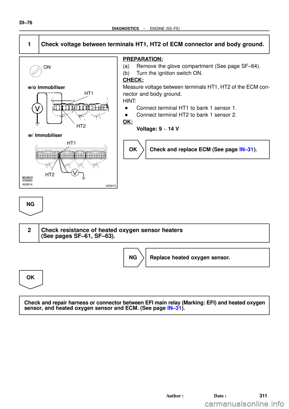
1 Check voltage between terminals HT1, HT2 of ECM connector and body ground.
PREPARATION:
(a) Remove the glove compartment (See page SF±64).
(b) Turn the ignition switch ON.
CHECK:
Measure voltage between terminals HT1, HT2 of the ECM con-
nector and body ground.
HINT:
�Connect terminal HT1 to bank 1 sensor 1.
�Connect terminal HT2 to bank 1 sensor 2.
OK:
Voltage: 9 ~ 14 V
OK Check and replace ECM (See page IN±31).
NG
2 Check resistance of heated oxygen sensor heaters
(See pages SF±61, SF±63).
NG Replace heated oxygen sensor.
OK
Check and repair harness or connector between EFI main relay (Marking: EFI) and heated oxygen
sensor, and heated oxygen sensor and ECM. (See page IN±31).
Page 2498 of 4770
DI±78
± DIAGNOSTICSENGINE (5S±FE)
313 Author�: Date�:
2 Check for open and short in harness and connector between ECM and heated
oxygen sensor (See page IN±31).
NG Repair or replace harness or connector.
OK
3 Check output voltage of heated oxygen sensor.
PREPARATION:
(a) Connect the OBD II scan tool or TOYOTA hand±held tester to the DLC3.
(b) Warm up the engine to normal operating temp.
CHECK:
Read voltage output of the heated oxygen sensor when the engine suddenly raced.
HINT:
Perform quick racing to 4,000 rpm 3 min. using the accelerator pedal.
OK:
Heated oxygen sensor output voltage:
Alternates from 0.45*
1/0.40*2 V or less to 0.60*1/0.50*2 V or more.
*1: for California Spec.
*
2: except California Spec.
OK Check that each connector is properly
connected.
NG
Replace heated oxygen sensor.
Page 2500 of 4770
DI±80
± DIAGNOSTICSENGINE (5S±FE)
315 Author�: Date�: �
OBD II scan tool (excluding TOYOTA hand±held tester) displays the one fifth of the A/F sensor output
voltage which is displayed on the TOYOTA hand±held tester.
INSPECTION PROCEDURE
HINT:
Read freeze frame data using TOYOTA hand±held tester or OBD II scan tool. Because freeze frame records
the engine conditions when the malfunction is detected, when troubleshooting it is useful for determining
whether the vehicle was running or stopped, the engine warmed up or not, the airÅfuel ratio lean or rich, etc.
at the time of the malfunction.
1 Check air induction system (See page SF±1).
NG Repair or replace.
OK
2 Check injector injection (See page SF±23).
NG Replace injector.
OK
3 Check manifold absolute pressure sensor and engine coolant temp. sensor
(See pages SF±53 and SF±49).
NG Repair or replace.
OK
4 Check for spark and ignition (See page IG±1).
NG Repair or replace.
OK
Page 2501 of 4770
± DIAGNOSTICSENGINE (5S±FE)
DI±81
316 Author�: Date�:
5 Check fuel pressure (See page SF±6).
NG Check and repair fuel pump, pressure regulator,
fuel pipe line and filter.
OK
6 Check gas leakage on exhaust system.
NG Repair or replace.
OK
Check and replace ECM (See page IN±31).
Page 2502 of 4770

317 Author�: Date�:
7 Check output voltage of A/F sensor.
PREPARATION:
(a) Connect the OBD II scan tool or TOYOTA hand±held tester to the DLC3.
(b) Warm up the A")
DI±82
± DIAGNOSTICSENGINE (5S±FE)
317 Author�: Date�:
7 Check output voltage of A/F sensor.
PREPARATION:
(a) Connect the OBD II scan tool or TOYOTA hand±held tester to the DLC3.
(b) Warm up the A/F sensor with the engine at 2,500 rpm for approx. 90 sec.
CHECK:
Read voltage value of A/F sensor on the screen of OBD II scan tool or TOYOTA hand±held tester when you
perform all the following conditions.
HINT:
The voltage of AF� terminal of ECM is 3.3 V fixed and AF� terminal is 3.0 V fixed. Therefore, it is impossible
to check the A/F sensor output voltage at the terminals (AF�/AF�) of ECM.
OK:
ConditionA/F Sensor Voltage value
Engine idling
Engine racing�Not remains at 3.30 V (* 0.660 V)
�Not remains at38V(*0 76 V) or moreDriving at engine speed 1,500 rpm or more and vehicle
speed 40 km/h (25 mph) or more, and operate throttle valve
open and close�Not remains at 3.8 V (* 0.76 V) or more
�Not remains at 2.8 V (* 0.56 V) or less
*: When you use OBD II scan tool (excluding TOYOTA hand±held tester)
HINT:
�During fuel enrichment, there is a case that the output voltage of A/F sensor is below 2.8 V (* 0.56 V),
it is normal.
�During fuel cut, there is a case that the output voltage of A/F sensor is above 3.8 V (* 0.76 V), it is nor-
mally.
�If output voltage of A/F sensor remains at 3.30 V (* 0.660 V) even after performing all the above condi-
tions, A/F sensor circuit may be open.
�If output voltage of A/F sensor remains at 3.8 V (* 0.76 V) or more, or 2.8 V (* 0.56 V) or less even after
performing all the above conditions, A/F sensor circuit may be short.
*: When you use the OBD II scan tool (excluding TOYOTA hand±held tester).
OK Go to step 9.
NG
Page 2503 of 4770
± DIAGNOSTICSENGINE (5S±FE)
DI±83
318 Author�: Date�:
8 Check for open and short in harness and connector between ECM and oxygen
sensor (See page IN±31).
NG Repair or replace harness or connector.
OK
Replace A/F sensor.
9 Perform confirmation driving pattern (See page DI±152).
Go
10 Is there DTC P0171 or P0172 being output again?
YES Check and replace ECM.
NO
11 Did vehicle runs out of fuel in the past?
NO Check for intermittent problems.
YES
DTC P0171 or P0172 is caused by running out of fuel.