Page 2431 of 4770
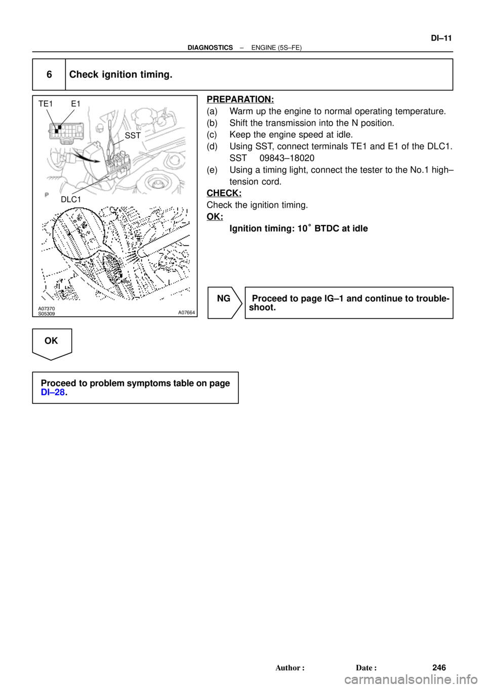
A07370S05309A07664
E1 TE1
SST
DLC1
± DIAGNOSTICSENGINE (5S±FE)
DI±11
246 Author�: Date�:
6 Check ignition timing.
PREPARATION:
(a) Warm up the engine to normal operating temperature.
(b) Shift the transmission into the N position.
(c) Keep the engine speed at idle.
(d) Using SST, connect terminals TE1 and E1 of the DLC1.
SST 09843±18020
(e) Using a timing light, connect the tester to the No.1 high±
tension cord.
CHECK:
Check the ignition timing.
OK:
Ignition timing: 10° BTDC at idle
NG Proceed to page IG±1 and continue to trouble-
shoot.
OK
Proceed to problem symptoms table on page
DI±28.
Page 2432 of 4770
S05327Fuel Inlet Hose
DI±12
± DIAGNOSTICSENGINE (5S±FE)
247 Author�: Date�:
7 Check fuel pressure.
PREPARATION:
(a) Be sure that enough fuel is in the tank.
(b) Connect the TOYOTA hand±held tester to the DLC3.
(c) Turn the ignition switch ON and push TOYOTA hand±held
tester main switch ON.
(d) Use the ACTIVE TEST mode to operate the fuel pump.
(e) Please refer to the TOYOTA hand±held tester operator's
manual for further details.
(f) If you have no TOYOTA hand±held tester, connect the
positive (+) and negative (±) leads from the battery to the
fuel pump connector (See page SF±6).
CHECK:
Check for fuel pressure in the fuel inlet hose when it is pinched
off.
HINT:
At this time, you will hear a fuel flowing noise.
NG Proceed to page SF±6 and continue to trouble-
shoot.
OK
Page 2433 of 4770
A00359
± DIAGNOSTICSENGINE (5S±FE)
DI±13
248 Author�: Date�:
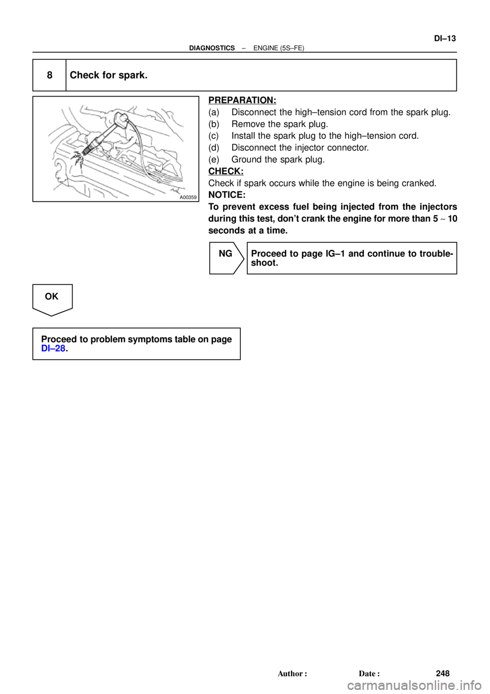
8 Check for spark.
PREPARATION:
(a) Disconnect the high±tension cord from the spark plug.
(b) Remove the spark plug.
(c) Install the spark plug to the high±tension cord.
(d) Disconnect the injector connector.
(e) Ground the spark plug.
CHECK:
Check if spark occurs while the engine is being cranked.
NOTICE:
To prevent excess fuel being injected from the injectors
during this test, don't crank the engine for more than 5 ~ 10
seconds at a time.
NG Proceed to page IG±1 and continue to trouble-
shoot.
OK
Proceed to problem symptoms table on page
DI±28.
Page 2436 of 4770

251 Author�: Date�:
DIAGNOSTIC TROUBLE CODE CHART
HINT:
Parameters listed in the chart may not be exactly the same as your reading due to the type of ins")
DI00I±09
DI±16
± DIAGNOSTICSENGINE (5S±FE)
251 Author�: Date�:
DIAGNOSTIC TROUBLE CODE CHART
HINT:
Parameters listed in the chart may not be exactly the same as your reading due to the type of instrument
or other factors.
If a malfunction code is displayed during the DTC check in check mode, check the circuit for that code listed
in the table below. For details of each code, turn to the page referred to under the ''See Page '' for the respec-
tive ''DTC No.'' in the DTC chart.
SAE Controlled:
DTC No.
(See Page)Detection ItemTrouble AreaMIL*1Memory
P0105
(DI±29)
Manifold Absolute
Pressure/Barometric
Pressure Circuit
Malfunction�Open or short in manifold absolute pressure sensor circuit
�Manifold absolute pressure sensor
�ECM
��
P0106
(DI±33)Manifold Absolute Pressure
Circuit Range/Performance
Problem�Manifold absolute pressure sensor
�Vacuum line��
P0110
(DI±35)Intake Air Temp. Circuit
Malfunction�Open or short in intake air temp. sensor circuit
�Intake air temp. sensor (built into mass air flow meter)
�ECM
��
P0115
(DI±41)Engine Coolant Temp. Circuit
Malfunction�Open or short in engine coolant temp. sensor circuit
�Engine coolant temp. sensor
�ECM
��
P0116
(DI±47)Engine Coolant Temp. Circuit
Range/Performance Problem�Engine coolant temp. sensor
�Cooling system��
P0120
(DI±49)Throttle/Pedal Position
Sensor/Switch ºAº Circuit
Malfunction�Open or short in throttle position sensor circuit
�Throttle position sensor
�ECM
��
P0121
(DI±54)Throttle/Pedal Position
Sensor/Switch ºAº Circuit
Range/Performance Problem
�Throttle position sensor��
*2
P0125
(DI±61)
Insufficient Coolant Temp. for
Closed Loop Fuel Control
(Except California Spec.)�Open or short in heated oxygen sensor (bank 1 sensor 1)
circuit
�Heated oxygen sensor (bank 1 sensor 1)
�ECM
��
*3
P0125
(DI±55)
Insufficient Coolant Temp. for
Closed Loop Fuel Control
(Only for California Spec.)�Open or short in A/F sensor circuit
�A/F sensor
�ECM
��
*2
P0130
(DI±66)Heated Oxygen Sensor Circuit
Malfunction (Bank 1 Sensor 1)�Heated oxygen sensor
�Fuel trim malfunction��
*2
P0133
(DI±71)
Heated Oxygen Sensor Circuit
Slow Response
(Bank 1 Sensor 1)�Heated oxygen sensor
�Fuel trim malfunction��
*2
P0135
(DI±75)
Heated Oxygen Sensor Heater
Circuit Malfunction
(Bank 1 Sensor 1)�Open or short in heater circuit of heated oxygen sensor
�Heated oxygen sensor heater
� ECM
��
*1: ����� MIL lights up
*
2: Except California specification vehicles
*
3: Only for California specification vehicles
Page 2438 of 4770

253 Author�: Date�:
DTC No.
(See Page)Detection ItemTrouble AreaMIL*1Memory
P0340
(DI±103)Camshaft Position Sensor
Circuit Malfunction
�Open or short in camsha")
DI±18
± DIAGNOSTICSENGINE (5S±FE)
253 Author�: Date�:
DTC No.
(See Page)Detection ItemTrouble AreaMIL*1Memory
P0340
(DI±103)Camshaft Position Sensor
Circuit Malfunction
�Open or short in camshaft position sensor circuit
�Camshaft position sensor
�Distributor
�Starter
�ECM
��
P0401
(DI±105)Exhaust Gas Recirculation
Flow Insufficient Detected
�EGR valve stuck closed
�Open or short in VSV circuit for EGR
�Vacuum or EGR hose disconnected
�Manifold absolute pressure sensor
�EGR VSV open or close malfunction
�ECM
��
P0402
(DI±113)Exhaust Gas Recirculation
Flow Excessive Detected
�EGR valve stuck open
�Vacuum or EGR hose is connected to wrong post
�Manifold absolute pressure sensor
�ECM
��
*2
P0420
(DI±116)
Catalyst System Efficiency
Below Threshold
(Except California Spec.)�Three±way catalytic converter
�Open or short in heated oxygen sensor circuit
�Heated oxygen sensor
��
*3
P0420
(DI±119)
Catalyst System Efficiency
Below Threshold
(Only for California Spec.)
�Three±way catalystic converter
�Open short in heated oxygen sensor (bank 1 sensor 2) circuit
�Heated oxygen sensor (bank 1 sensor 2)
�Open or short in A/F sensor circuit
�A/F sensor
��
P0440
(DI±122)Evaporative Emission Control
System Malfunction
�Vapor pressure sensor
�Fuel tank cap incorrectly installed
�Fuel tank cap cracked or damaged
�Vacuum hose cracked, holed, blocked, damaged or
disconnected ((1) or (2) in fig. 1)
�Hose or tube cracked, holed, damaged or loose seal
((3) in fig. 1)
�Fuel tank cracked, holed or damaged
�Charcoal canister cracked, holed or damaged
�Fuel tank over fill check valve cracked or damaged
��
P0441
(DI±129)Evaporative Emission Control
System Incorrect Purge Flow
�Open or short in VSV circuit for vapor pressure sensor
�VSV for vapor pressure sensor
�Open or short in vapor pressure sensor circuit
�Vapor pressure sensor
O h t i VSV i it f EVAP
��
P0446
(DI±129)Evaporative Emission Control
System Vent Control
Malfunction
�Open or short in VSV circuit for EVAP
�VSV for EVAP
�Vacuum hose cracks, hole, blocked, damaged or disconnected
((1), (4), (5) holed (6) and (7) in fig. 1)
�Charcoal canister cracked, holed or damaged
�Fuel tank over fill check valve cracked or damaged
��
P0450
(DI±142)Evaporative Emission Control
System Pressure Sensor
Malfunction
�Open or short in vapor pressure sensor circuit
V
��
P0451
(DI±142)Evaporative Emission Control
System Pressure Sensor
(Range/performance)�Vapor pressure sensor
�ECM
��
*1: ����� MIL lights up
*
2: Except California Specification vehicles
*
3: Only for California Specification vehicles
Page 2451 of 4770
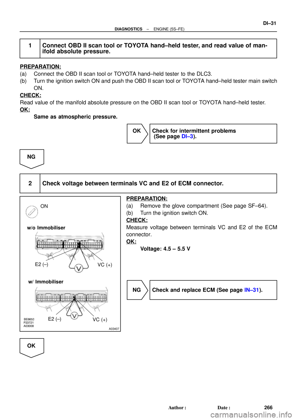
BE6653P23721A03008A03407
w/o Immobiliser
w/ ImmobiliserE2 (±)
VC (+)
ON
E2 (±)
VC (+)
± DIAGNOSTICSENGINE (5S±FE)
DI±31
266 Author�: Date�:
1 Connect OBD II scan tool or TOYOTA hand±held tester, and read value of man-
ifold absolute pressure.
PREPARATION:
(a) Connect the OBD II scan tool or TOYOTA hand±held tester to the DLC3.
(b) Turn the ignition switch ON and push the OBD II scan tool or TOYOTA hand±held tester main switch
ON.
CHECK:
Read value of the manifold absolute pressure on the OBD II scan tool or TOYOTA hand±held tester.
OK:
Same as atmospheric pressure.
OK Check for intermittent problems
(See page DI±3).
NG
2 Check voltage between terminals VC and E2 of ECM connector.
PREPARATION:
(a) Remove the glove compartment (See page SF±64).
(b) Turn the ignition switch ON.
CHECK:
Measure voltage between terminals VC and E2 of the ECM
connector.
OK:
Voltage: 4.5 ± 5.5 V
NG Check and replace ECM (See page IN±31).
OK
Page 2452 of 4770
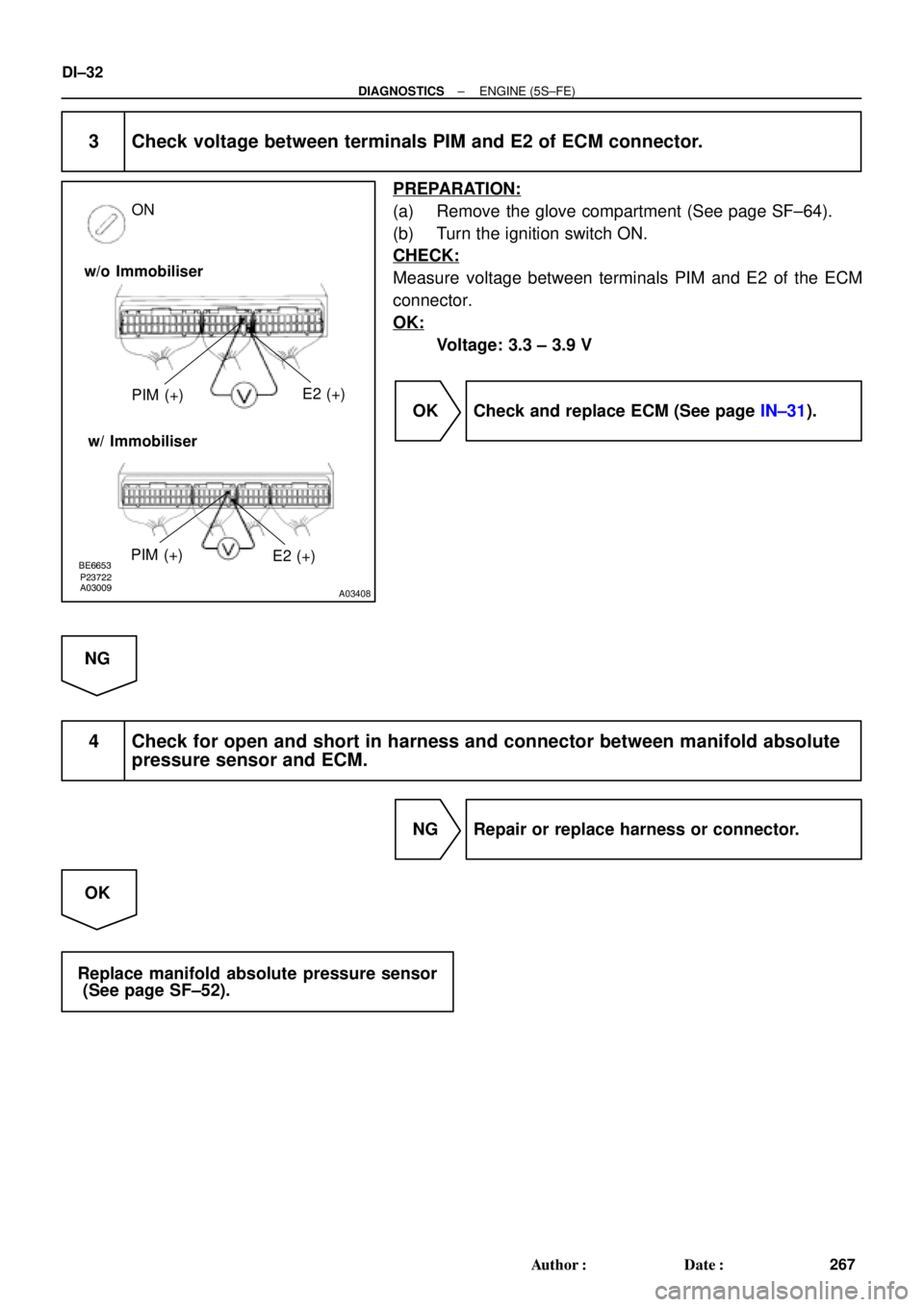
BE6653P23722A03009A03408
w/o Immobiliser
w/ ImmobiliserPIM (+)E2 (+)
ON
PIM (+)
E2 (+)
DI±32
± DIAGNOSTICSENGINE (5S±FE)
267 Author�: Date�:
3 Check voltage between terminals PIM and E2 of ECM connector.
PREPARATION:
(a) Remove the glove compartment (See page SF±64).
(b) Turn the ignition switch ON.
CHECK:
Measure voltage between terminals PIM and E2 of the ECM
connector.
OK:
Voltage: 3.3 ± 3.9 V
OK Check and replace ECM (See page IN±31).
NG
4 Check for open and short in harness and connector between manifold absolute
pressure sensor and ECM.
NG Repair or replace harness or connector.
OK
Replace manifold absolute pressure sensor
(See page SF±52).
Page 2454 of 4770
DI±34
± DIAGNOSTICSENGINE (5S±FE)
269 Author�: Date�:
2 Check manifold absolute pressure sensor operation (See page SF±52).
OK Check vacuum line between intake air chamber
and manifold absolute pressure sensor.
NG
Replace manifold absolute pressure sensor.