Page 2397 of 4770
P13014
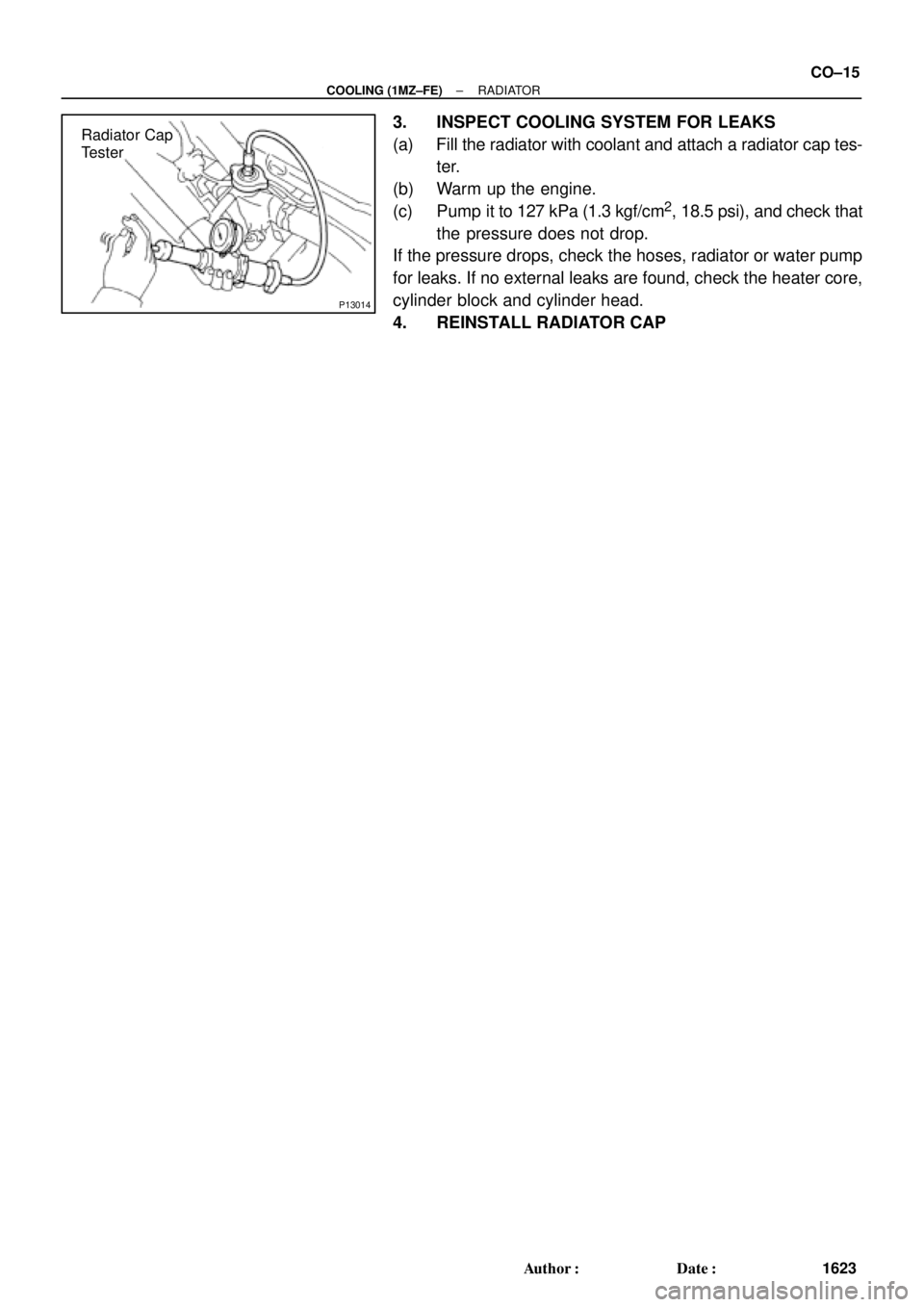
Radiator Cap
Tester
± COOLING (1MZ±FE)RADIATOR
CO±15
1623 Author�: Date�:
3. INSPECT COOLING SYSTEM FOR LEAKS
(a) Fill the radiator with coolant and attach a radiator cap tes-
ter.
(b) Warm up the engine.
(c) Pump it to 127 kPa (1.3 kgf/cm
2, 18.5 psi), and check that
the pressure does not drop.
If the pressure drops, check the hoses, radiator or water pump
for leaks. If no external leaks are found, check the heater core,
cylinder block and cylinder head.
4. REINSTALL RADIATOR CAP
Page 2400 of 4770
RADIATOR
1626 Author�: Date�:
REMOVAL
HINT:
�At the time of installation, please refer to the following
items.
�Start the")
CO03O±03
S04725
B05937
Lower
Hose
Oil
Cooler
Hose
CO±18
± COOLING (1MZ±FE)RADIATOR
1626 Author�: Date�:
REMOVAL
HINT:
�At the time of installation, please refer to the following
items.
�Start the engine, and check for coolant and A/T fluid
leaks.
�Check the A/T fluid level. (See page DI±438)
1. DRAIN ENGINE COOLANT
2. CANADA:
DISCONNECT RELAY BLOCK (FOR DAYTIME
RUNNING LIGHT SYSTEM) FROM BATTERY
HOLD±DOWN CLAMP
3. DISCONNECT UPPER RADIATOR HOSE FROM
RADIATOR
4. DISCONNECT LOWER RADIATOR HOSE FROM
WATER INLET PIPE
5. DISCONNECT A/T OIL COOLER HOSES FROM OIL
COOLER PIPES
6. DISCONNECT NO.1 AND NO.2 COOLING FAN
CONNECTORS
7. DISCONNECT NO.1 ECT SWITCH WIRE CONNECTOR
8. REMOVE RADIATOR AND COOLING FANS
ASSEMBLY
(a) Remove the 2 bolts and 2 upper supports.
Torque: 12.8 N´m (130 kgf´cm, 9 ft´lbf)
(b) Lift out the radiator, and remove the radiator and cooling
fans assembly.
(c) Remove the 2 lower supports.
9. REMOVE A/T OIL COOLER HOSES FROM
RADIATOR
10. REMOVE LOWER RADIATOR HOSE FROM
RADIATOR
Page 2407 of 4770
ELECTRIC COOLING FAN
CO±25
1633 Author�: Date�:
ELECTRIC COOLING FAN
ON±VEHICLE INSPECTION
1. CHECK COOLING FAN O")
B05939
CO03S±03
S04727
Disconnect
B05940
B05941
Ammeter
Battery
± COOLING (1MZ±FE)ELECTRIC COOLING FAN
CO±25
1633 Author�: Date�:
ELECTRIC COOLING FAN
ON±VEHICLE INSPECTION
1. CHECK COOLING FAN OPERATION WITH LOW
TEMPERATURE (Below 88°C (190°F))
(a) Turn the ignition switch ON.
(b) Check that the cooling fan stops.
If not, check the cooling fan relay and ECT switch, and check
for a separated connector or severed wire between the cooling
fan relay and ECT switch.
(c) Disconnect the No.1 ECT switch connector.
(d) Check that the cooling fan rotates.
If not, check the fuses, engine main relay, cooling fan relay,
cooling fan, and check for a short circuit between the cooling
fan relay and ECT switch.
(e) Reconnect the No.1 ECT switch connector.
2. CHECK COOLING FAN OPERATION WITH HIGH
TEMPERATURE (Above 98°C (208°F))
(a) Start the engine, and raise coolant temperature to above
98°C (208°F).
(b) Check that the cooling fan rotates.
If not, replace the No.1 ECT switch.
3. INSPECT NO.1 COOLING FAN
(a) Disconnect the cooling fan connector.
(b) Connect battery and ammeter to the cooling fan connec-
tor.
(c) Check that the cooling fan rotates smoothly, and check
the reading on the ammeter.
Standard amperage: 8.3 ± 11.3 A at 20°C (68°F)
(d) Reconnect the cooling fan connector.
Page 2416 of 4770
ENGINE COOLANT TEMPERATURE (ECT) SWITCH
1642 Author�: Date�:
ENGINE COOLANT
TEMPERATUR")
CO03Y±04
S04602No.1 ECT Switch
P01924
Ohmmeter
S04601
No.2 ECT
Switch
P06722
Ohmmeter CO±34
± COOLING (1MZ±FE)ENGINE COOLANT TEMPERATURE (ECT) SWITCH
1642 Author�: Date�:
ENGINE COOLANT
TEMPERATURE (ECT) SWITCH
INSPECTION
1. DRAIN ENGINE COOLANT
2. INSPECT NO.1 ECT SWITCH
(a) Remove the No.1 ECT switch.
(b) Inspect the No.1 ECT switch.
(1) Using an ohmmeter, check that there is no continu-
ity between the terminals when the coolant temper-
ature is above 98°C (208°F).
If there is continuity, replace the switch.
(2) Check that there is continuity, between the termi-
nals when the coolant temperature is below 88°C
(190°F).
If there is no continuity, replace the switch.
(c) Reinstall the No.1 ECT switch.
3. INSPECT NO.2 ECT SWITCH
(a) Remove the No.2 ECT switch.
(b) Inspect the No.2 ECT switch.
(1) Using an ohmmeter, check that there is continuity
between terminals when the coolant temperature is
above 94°C (201°F).
If there is no continuity, replace the switch.
(2) Check that there is no continuity between the termi-
nals when the coolant temperature is below 83°C
(181°F).
If there is continuity, replace the switch.
(c) Reinstall the No.2 ECT switch.
Page 2417 of 4770
± COOLING (1MZ±FE)ENGINE COOLANT TEMPERATURE (ECT) SWITCH
CO±35
1643 Author�: Date�:
4. REFILL ENGINE COOLANT
5. START ENGINE AND CHECK FOR COOLANT LEAKS
Page 2418 of 4770

S05391
Engine
Main Relay
CO03Z±03
S04974
Ohmmeter
1
Continuity OhmmeterOhmmeter Continuity
No
Continuity 2
5
43
S04973
Ohmmeter
1
Ohmmeter
Continuity No
Continuity
2
5
43
Battery CO±36
± COOLING (1MZ±FE)ENGINE MAIN RELAY
1644 Author�: Date�:
ENGINE MAIN RELAY
INSPECTION
1. REMOVE RELAY BOX COVER
2. REMOVE ENGINE MAIN RELAY
(Marking: ENGINE MAIN)
3. INSPECT RELAY CONTINUITY
(a) Using an ohmmeter, check that there is continuity be-
tween terminals 3 and 5.
If there is no continuity, replace the relay.
(b) Check that there is continuity between terminals 2 and 4.
If there is no continuity, replace the relay.
(c) Check that there is no continuity between terminals 1 and
2.
If there is continuity, replace the relay.
4. INSPECT RELAY OPERATION
(a) Apply battery positive voltage across terminals 3 and 5.
(b) Using an ohmmeter, check that there is no continuity be-
tween terminals 2 and 4.
If there is continuity, replace the relay.
(c) Check that there is continuity between terminals 1 and 2.
If there is no continuity, replace the relay.
5. REINSTALL ENGINE MAIN RELAY
6. REINSTALL RELAY BOX COVER
Page 2421 of 4770

DI00F±08
Vehicle Brought to Workshop
Customer Problem Analysis P. DI±2
Problem Symptom Confirmation
If the engine does not start perform steps 10 and 12 firstConnect the OBD II scan tool or TOYOTA hand±held tester to DLC3 P. DI±3
If the display indicates a communication fault in the tool, inspect DLC3 P. DI±3
Check DTC and Freezed Frame Data (Precheck)
Record or Print DTC and Freezed Frame Data P. DI±3
Clear DTC and Freezed Frame Data P. DI±3
Visual Inspection
Setting the Check Mode Diagnosis P. DI±3
Symptom Simulation P. IN±21
Basic Inspection P. DI±3DTC Chart P. DI±16
Problem Symptoms Table P. DI±28
Circuit Inspection P. DI±29
Adjustment, Repair
DTC Check P. DI±3
Titles insideare titles of pages in
in the bottom portion. See the indicated
pages for detailed explanations.this manual with the page number indicated
Malfunction
occurs.Malfunction does not occur.
Parts Inspection
Check for Intermittent Problems P. DI±3
Identification of Problem
Confirmation Test
End 1
2
3
4
5
6
7
108
9
11
12
13
15 14
16
Normal Malfunction code.
17
± DIAGNOSTICSENGINE (5S±FE)
DI±1
236 Author�: Date�:
ENGINE (5S±FE)
HOW TO PROCEED WITH TROUBLESHOOTING
Troubleshoot in accordance with the procedure on the following page.
Page 2422 of 4770

DI00G±05
ENGINE CONTROL SYSTEM Check Sheet
Customer's Name
Driver's Name
Data Vehicle
Brought in
License No.
Model and Model
Year
Frame No.
Engine Model
Odometer Reading
Problem Symptoms
Engine does
not Start
Difficult to
Start
Poor Idling
Poor
Driveaability
Engine Stall
Others
Engine does not crankNo initial combustionNo complete combustion
Engine cranks slowly
Other
Incorrect first idleIdling rpm is abnormalHigh ( rpm)Low ( rpm)
Rough idling
Other
HesitationBack fireMuffler explosion (after±fire)Surging
Knocking
Other
Soon after startingAfter accelerator pedal depressed
After accelerator pedal released
During A/C operation
Shifting from N to D
Other
Datas Problem
Occurred
Problem Frequency
Condition When
Problem Occurs
Weather
Engine Operation
Engine Temperature Place Outdoor
TemperatureConstant
Sometimes ( times per day/month)Once only
Other
Fine
CloudyRainySnowyVarious/Other
Hot
Warm CoolCold (approx. °F/ °C)
Highway
SuburbsInner cityUphillDownhill
Rough road
Other
Cold
Warming upAfter warming upAny temperatureOther
Starting
Just after starting ( min.)IdlingRacing
Driving
Constant speedAccelerationDeceleration
A/C switch ON/OFF
Other
Condition of MILRemains on Sometimes light up Does not light up
NormalMalfunction code(s) (code )
Freezed frame data ( )
NormalMalfunction code(s) (code )
Freezed frame data ( )
Normal Mode
(Precheck)
Check Mode DTC InspectionInspector's
Name
km
miles
DI±2
± DIAGNOSTICSENGINE (5S±FE)
237 Author�: Date�:
CUSTOMER PROBLEM ANALYSIS CHECK