Page 361 of 4770

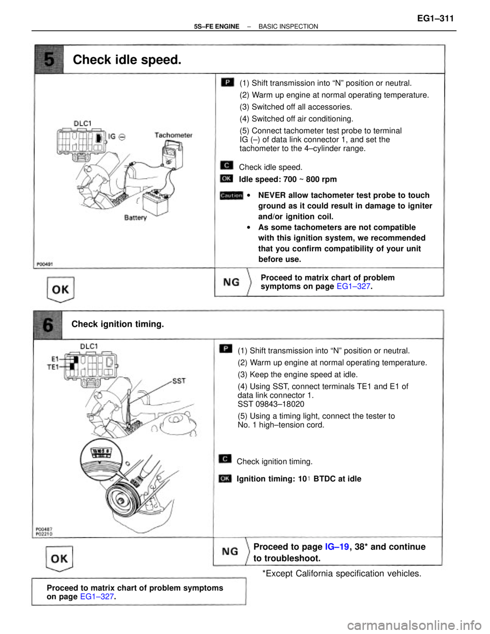
(1) Shift transmission into ªNº position or neutral.
(2) Warm up engine at normal operating temperature.
(3) Keep the engine speed at idle.
(4) Using SST, connect terminals TE1 and E1 of
data link connector 1.
SST 09843±18020
(5) Using a timing light, connect the tester to
No. 1 high±tension cord.(1) Shift transmission into ªNº position or neutral.
(2) Warm up engine at normal operating temperature.
(3) Switched off all accessories.
(4) Switched off air conditioning.
(5) Connect tachometer test probe to terminal
IG (±) of data link connector 1, and set the
tachometer to the 4±cylinder range.
wNEVER allow tachometer test probe to touch
ground as it could result in damage to igniter
and/or ignition coil.
wAs some tachometers are not compatible
with this ignition system, we recommended
that you confirm compatibility of your unit
before use.
Proceed to matrix chart of problem symptoms
on page EG1±327.
Proceed to page IG±19, 38* and continue
to troubleshoot.
Proceed to matrix chart of problem
symptoms on page EG1±327.
*Except California specification vehicles. Check ignition timing.
Check idle speed.
Check idle speed.
Idle speed: 700 ~ 800 rpm
Check ignition timing.
Ignition timing: 10� BTDC at idle
± 5S±FE ENGINEBASIC INSPECTIONEG1±311
Page 403 of 4770

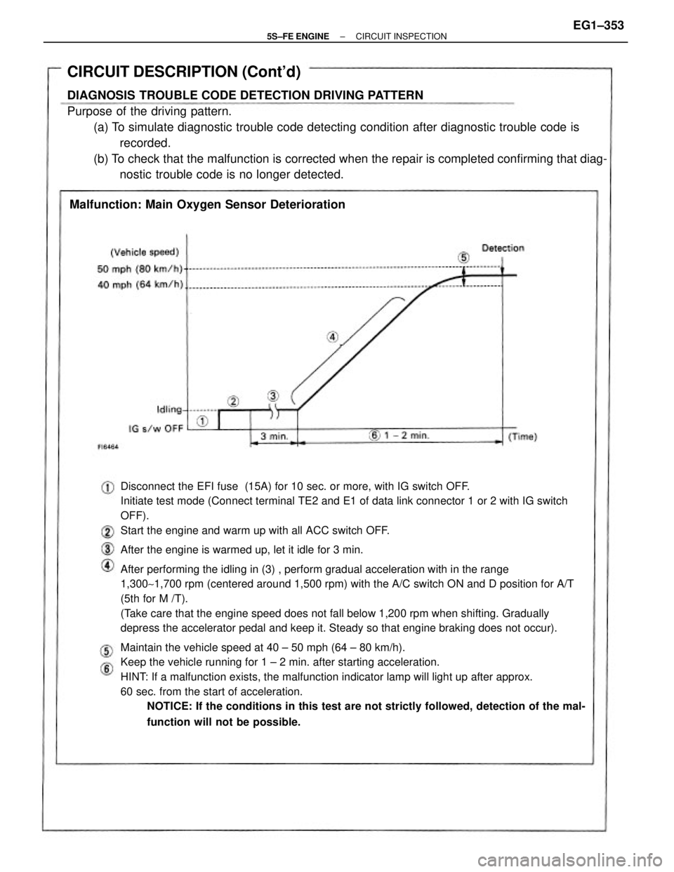
Disconnect the EFI fuse (15A) for 10 sec. or more, with IG switch OFF.
Initiate test mode (Connect terminal TE2 and E1 of data link connector 1 or 2 with IG switch
OFF).
Start the engine and warm up with all ACC switch OFF.
After the engine is warmed up, let it idle for 3 min.
After performing the idling in (3) , perform gradual acceleration with in the range
1,300~1,700 rpm (centered around 1,500 rpm) with the A/C switch ON and D position for A/T
(5th for M /T).
(Take care that the engine speed does not fall below 1,200 rpm when shifting. Gradually
depress the accelerator pedal and keep it. Steady so that engine braking does not occur).
Maintain the vehicle speed at 40 ± 50 mph (64 ± 80 km/h).
Keep the vehicle running for 1 ± 2 min. after starting acceleration.
HINT: If a malfunction exists, the malfunction indicator lamp will light up after approx.
60 sec. from the start of acceleration.
NOTICE: If the conditions in this test are not strictly followed, detection of the mal-
function will not be possible.
CIRCUIT DESCRIPTION (Cont'd)
DIAGNOSIS TROUBLE CODE DETECTION DRIVING PATTERN
Purpose of the driving pattern.
(a) To simulate diagnostic trouble code detecting condition after diagnostic trouble code is
recorded.
(b) To check that the malfunction is corrected when the repair is completed confirming that diag-
nostic trouble code is no longer detected.
Malfunction: Main Oxygen Sensor Deterioration
± 5S±FE ENGINECIRCUIT INSPECTIONEG1±353
Page 414 of 4770

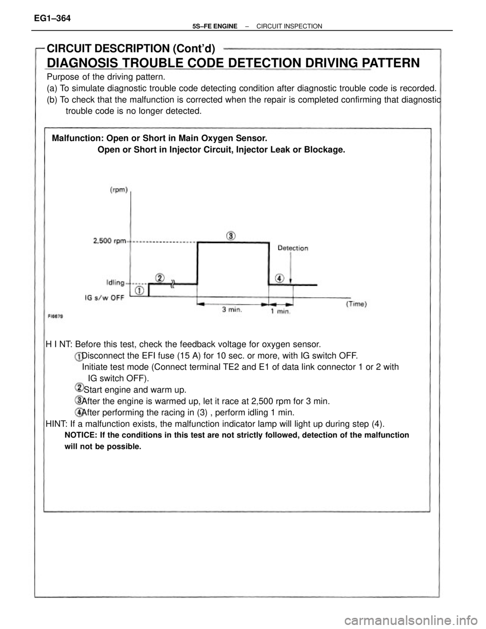
H I NT: Before this test, check the feedback voltage for oxygen sensor.
Disconnect the EFI fuse (15 A) for 10 sec. or more, with IG switch OFF.
Initiate test mode (Connect terminal TE2 and E1 of data link connector 1 or 2 with
IG switch OFF).
Start engine and warm up.
After the engine is warmed up, let it race at 2,500 rpm for 3 min.
After performing the racing in (3) , perform idling 1 min.
HINT: If a malfunction exists, the malfunction indicator lamp will light up during step (4).
NOTICE: If the conditions in this test are not strictly followed, detection of the malfunction
will not be possible.
CIRCUIT DESCRIPTION (Cont'd)
DIAGNOSIS TROUBLE CODE DETECTION DRIVING PATTERN
Purpose of the driving pattern.
(a) To simulate diagnostic trouble code detecting condition after diagnostic trouble code is recorded.
(b) To check that the malfunction is corrected when the repair is completed confirming that diagnostic
trouble code is no longer detected.
Malfunction: Open or Short in Main Oxygen Sensor.
Open or Short in Injector Circuit, Injector Leak or Blockage.
± 5S±FE ENGINECIRCUIT INSPECTIONEG1±364
Page 420 of 4770

Disconnect the E F I fuse (15 A) for 10 sec. or more, with IG switch OFF.
Initiate test mode (Connect terminals TE2 and E1 of data link connector 1 or 2
with I G switch OFF).
Start the engine and warm up, with all ACC switch OFF.
After the engine is warmed up, let it drive at 50 ~ 55 mph (80 ~ 88 km/h)
for 10 min. or more.
After driving, stop at a safe place and perform idling for 2 min. or less.
After performing the idling in (4) , perform acceleration to 60 mph (96 km/h)
with the throttle valve fully open.
HINT: If a malfunction exists, the malfunction indicator lamp will light up during
step.
NOTICE: If the conditions in this test are not strictly followed, detection of the
malfunction will not be possible.
CIRCUIT DESCRIPTION (Cont'd)
DIAGNOSIS TROUBLE CODE DETECTION DRIVING PATTERN
Purpose of the driving pattern.
(a) To simulate diagnostic trouble code detecting condition after diagnostic trouble code is
recorded.
(b) To check that the malfunction is corrected when the repair is completed confirming that diagnos±
tic trouble code is no longer detected.
Malfunction: Open or Short in Sub Oxygen Sensor
± 5S±FE ENGINECIRCUIT INSPECTIONEG1±370
Page 435 of 4770

If the ECM detects the above diagnosis conditions, it operates the fail safe function in which the
corrective retard angle value is set to the maximum value.
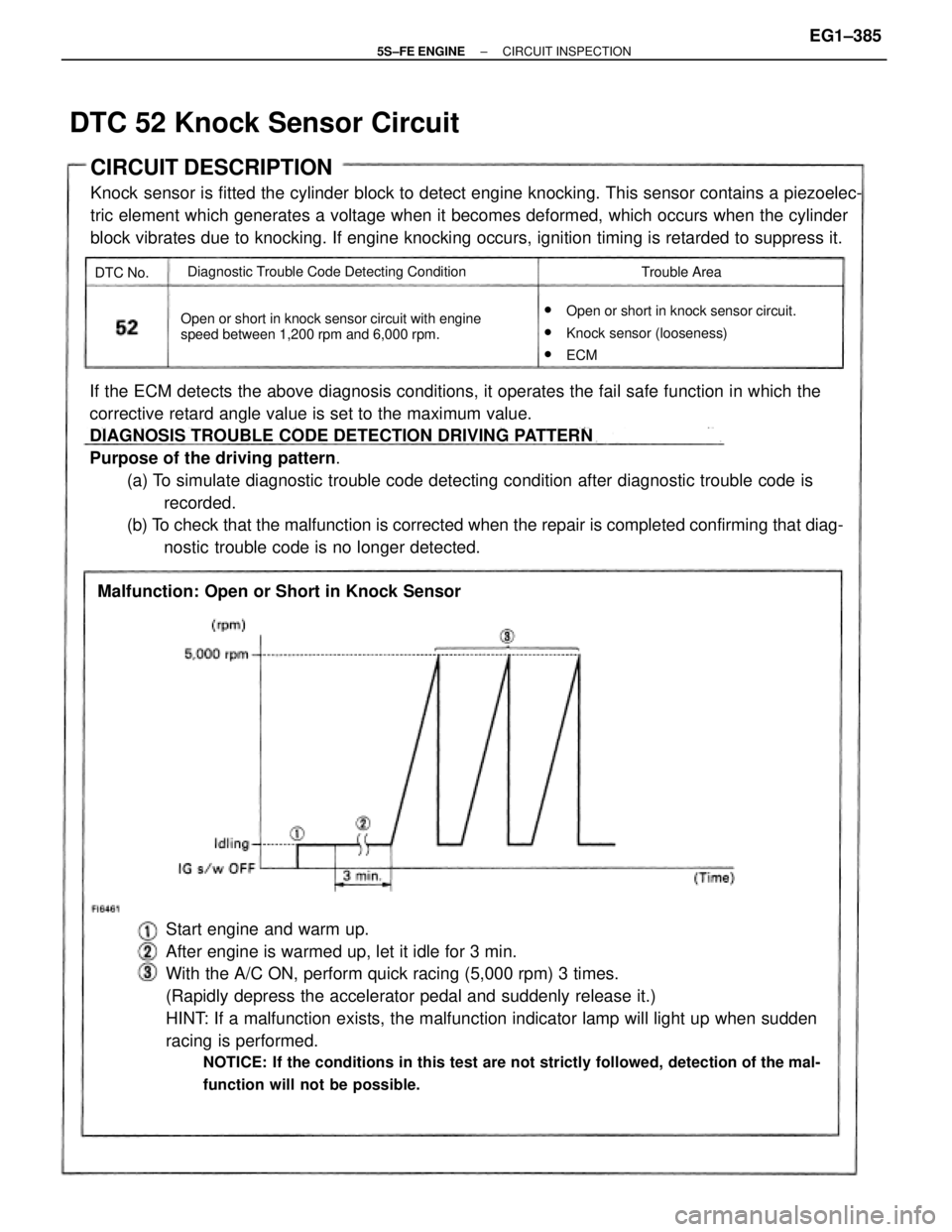
DIAGNOSIS TROUBLE CODE DETECTION DRIVING PATTERN
Purpose of the driving pattern.
(a) To simulate diagnostic trouble code detecting condition after diagnostic trouble code is
recorded.
(b) To check that the malfunction is corrected when the repair is completed confirming that diag-
nostic trouble code is no longer detected.
Start engine and warm up.
After engine is warmed up, let it idle for 3 min.
With the A/C ON, perform quick racing (5,000 rpm) 3 times.
(Rapidly depress the accelerator pedal and suddenly release it.)
HINT: If a malfunction exists, the malfunction indicator lamp will light up when sudden
racing is performed.
NOTICE: If the conditions in this test are not strictly followed, detection of the mal-
function will not be possible.
CIRCUIT DESCRIPTION
Knock sensor is fitted the cylinder block to detect engine knocking. This sensor contains a piezoelec-
tric element which generates a voltage when it becomes deformed, which occurs when the cylinder
block vibrates due to knocking. If engine knocking occurs, ignition timing is retarded to suppress it.
w
Open or short in knock sensor circuit.
wKnock sensor (looseness)
wECM Open or short in knock sensor circuit with engine
speed between 1,200 rpm and 6,000 rpm.
Malfunction: Open or Short in Knock Sensor
Diagnostic Trouble Code Detecting Condition
Trouble Area
DTC 52 Knock Sensor Circuit
DTC No.
± 5S±FE ENGINECIRCUIT INSPECTIONEG1±385
Page 441 of 4770

Disconnect the EFI fuse (15 A) for 10 sec. or more, with IG switch OFF. Initiate
test mode (Connect terminals TE2 and E1 of data link connector, 1 or 2 with IG
switch OFF).
CIRCUIT DESCRIPTION (Cont'd)
DIAGNOSIS TROUBLE CODE DETECTION DRIVING PATTERN
Purpose of the driving pattern.
(a) To simulate diagnostic trouble code detecting condition after diagnostic trouble code is
recorded.
(b) To check that the malfunction is corrected when the repair is completed confirming that diag-
nostic trouble code is no longer detected.
Malfunction: Open in EGR gas temp. sensor circuit
Start the engine and warm up.
After the engine is warmed up, let it idle for 3 min.
With the A/C ON and transmission in 5th gear A/T in ªDº position), drive at
55 ± 60 mph (88 ± 96 km/h) for 4 min. or less.
HINT: If a malfunction exists, the malfunction indicator lamp will light up dur-
ing step (4) .
NOTICE: If the conditions in this test are not strictly observed, detection of
the malfunction will not be possible.
± 5S±FE ENGINECIRCUIT INSPECTIONEG1±391
Page 560 of 4770
81CHASSISÐBRAKES
2) Initial Check
An initial check is carried out once every a few seconds after the ignition was turned on. The functions of each
solenoid valve and pump motor in the actuator are checked on order.
3) Self±Diagnosis
If the ABS & TRAC ECU detects a malfunction in the engine, ABS or TRAC system, it blinks the TRAC OFF
indicator light to alert the driver of the malfunction. At the same, the ABS & TRAC 1997 Avalon Repair Manual
(Pub. No. RM504U) for the diagnostic code check method, diagnostic code and diagnostic code clearance.
4) Fail±Safe
In the event of a malfunction in the engine, ABS or TRAC system, the ABS & ECU prohibits the TRAC system.
Thus, the brake and engine controls will operate in the same conditions as those without the TRAC system.
Page 789 of 4770

'99camry U
23
TESTING THE SYSTEM
1. Open all the windows.
2. Set the system as described above.
The doors should be locked with the
key or wireless remote control transmit-
ter. Be sure to wait until the indicator
light goes off or starts flashing.
3. Unlock any door from the inside. The
system should activate the alarm.
4. Stopping the alarm as described above.
5. Repeat this operation for the other
doors, trunk and hood. When testing on
the hood, also check that the system
is activated when the battery terminal
is disconnected and then reconnected.
If the system does not work properly,
have it checked by your Toyota dealer.
Fuel tank cap
1. To open the fuel filler door, pull the
lever up.
When refueling, turn off the engine.
CAUTION
�Do not smoke, cause sparks or al-
low open flames when refueling.
The fumes are flammable.
�When opening the cap, do not re-
move the cap quickly. In hot weath-
er, fuel under pressure could cause
injury by spraying out of the filler
neck if the cap is suddenly re-
moved.
2. To remove the fuel tank cap, turn
the cap slowly counterclockwise,
then pause slightly before removing
it. After removing the cap, hang it
on the cap hanger.
It is not unusual to hear a slight swoosh
when the cap is opened. When installing,
turn the cap clockwise till you hear a
click.
If the cap is not tightened securely, the
malfunction indicator lamp comes on.
Make sure the cap is tightened securely.