Page 121 of 4770
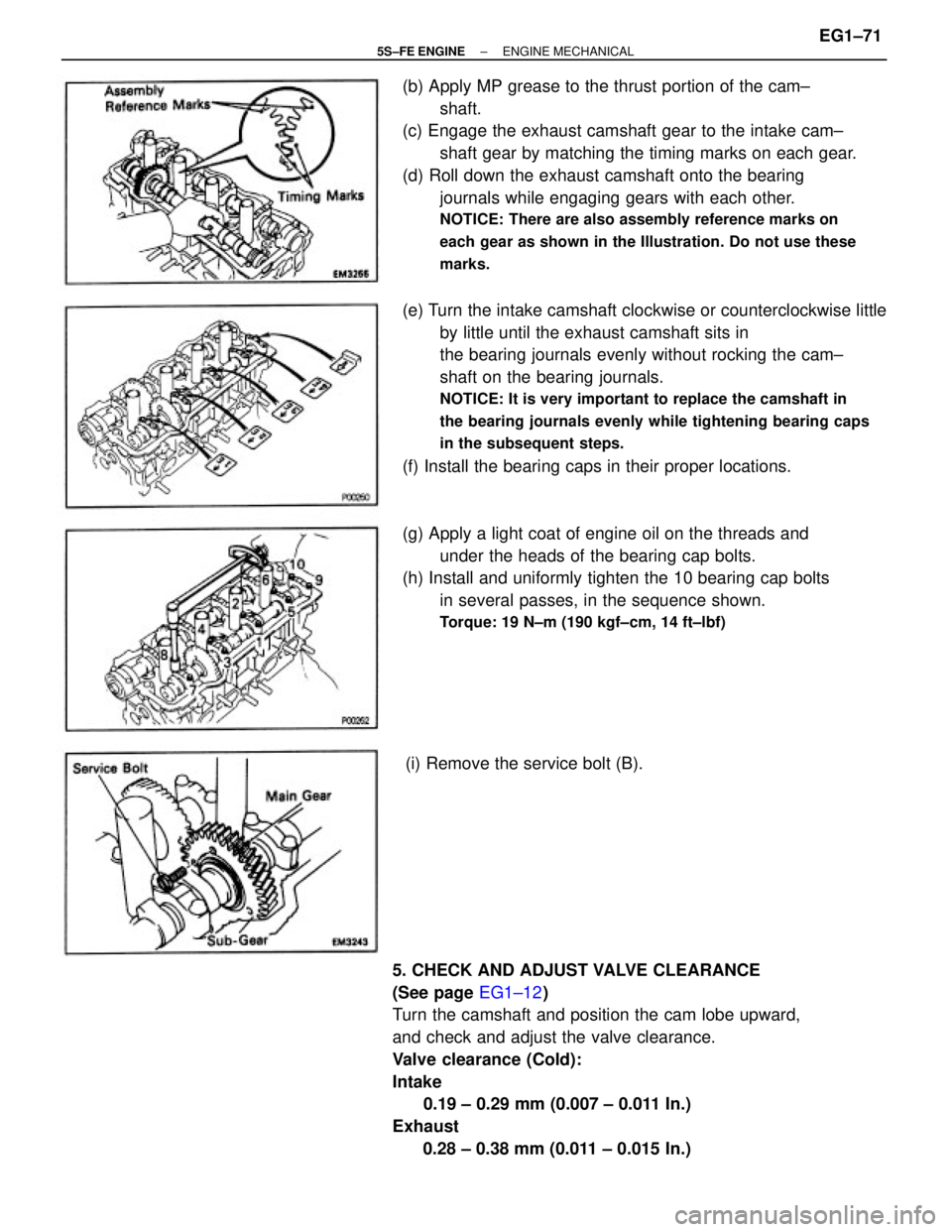
(b) Apply MP grease to the thrust portion of the cam±
shaft.
(c) Engage the exhaust camshaft gear to the intake cam±
shaft gear by matching the timing marks on each gear.
(d) Roll down the exhaust camshaft onto the bearing
journals while engaging gears with each other.
NOTICE: There are also assembly reference marks on
each gear as shown in the Illustration. Do not use these
marks.
5. CHECK AND ADJUST VALVE CLEARANCE
(See page EG1±12)
Turn the camshaft and position the cam lobe upward,
and check and adjust the valve clearance.
Valve clearance (Cold):
Intake
0.19 ± 0.29 mm (0.007 ± 0.011 In.)
Exhaust
0.28 ± 0.38 mm (0.011 ± 0.015 In.)(e) Turn the intake camshaft clockwise or counterclockwise little
by little until the exhaust camshaft sits in
the bearing journals evenly without rocking the cam±
shaft on the bearing journals.
NOTICE: It is very important to replace the camshaft in
the bearing journals evenly while tightening bearing caps
in the subsequent steps.
(f) Install the bearing caps in their proper locations.
(g) Apply a light coat of engine oil on the threads and
under the heads of the bearing cap bolts.
(h) Install and uniformly tighten the 10 bearing cap bolts
in several passes, in the sequence shown.
Torque: 19 N±m (190 kgf±cm, 14 ft±lbf)
(i) Remove the service bolt (B).
± 5S±FE ENGINEENGINE MECHANICALEG1±71
Page 124 of 4770
13. TEMPORARILY INSTALL NO.1 IDLER PULLEY AND
TENSION SPRING
(a) Install the pulley with the bolt. Do not tighten the bolt
yet.
HINT: Use bolt 42 mm (1.65 in.) in length.
(b) Install the tension spring.
(c) Pry the pulley toward the left as far as it will go and
tighten the bolt.
(d) Check that the idler pulley moves smoothly.
14. INSTALL CAMSHAFT TIMING PULLEY AND
TIMING BELT
(See page EG1±33)
15. INSTALL INJECTORS AND DELIVERY PIPE
(a) California:
Install new insulator and grommet to each injector.
(b) Except California:
Install a new grommet to each injector.
(c) California:
Apply a light coat of gasoline to 2 new 0±rings, and
install them to each injector.
(d) Except California:
Apply a light coat of gasoline to a new 0±ring, and
install it to each injector.
(e) While turning the injector left and right, install it to the
delivery pipes. Install the 4 injectors.
± 5S±FE ENGINEENGINE MECHANICALEG1±74
Page 145 of 4770
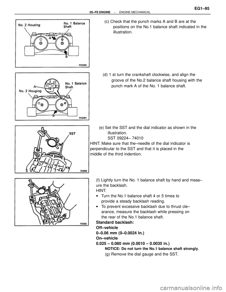
(f) Lightly turn the No. 1 balance shaft by hand and meas±
ure the backlash.
HINT:
wTurn the No.1 balance shaft 4 or 5 times to
provide a steady backlash reading.
wTo prevent excessive backlash due to thrust cle±
arance, measure the backlash while pressing on
the rear of the No.1 balance shaft.
Standard backlash:
Off±vehicle
0±0.06 mm (0±0.0024 In.)
On±vehicle
0.025 ± 0.080 mm (0.0010 ± 0.0035 in.)
NOTICE: Do not turn the No.1 balance shaft strongly.
(g) Remove the dial gauge and the SST. (e) Set the SST and the dial indicator as shown in the
illustration.
SST 09224± 74010
HINT: Make sure that the±needle of the dial indicator is
perpendicular to the SST and that it is placed in the
middle of the third indention.(d) 1 st turn the crankshaft clockwise, and align the
groove of the No.2 balance shaft housing with the
punch mark A of the No. 1 balance shaft. (c) Check that the punch marks A and B are at the
positions on the No.1 balance shaft indicated in the
illustration.
± 5S±FE ENGINEENGINE MECHANICALEG1±95
Page 148 of 4770
5. CHECK CONNECTING ROD THRUST CLEARANCE
Using a dial indicator, measure the thrust clearance
while moving the connecting rod back and forth.
Standard thrust clearance:
0.160 ± 0.312 mm (0.0063 ± 0.0123 in.)
Maximum thrust clearance:
0.36 mm (0.0138 in.)
If the thrust clearance is greater than maximum, re±
place the connecting rod assembly. If necessary, re±
place the crankshaft.
6. REMOVE CONNECTING ROD CAPS AND CHECK
OIL CLEARANCE
(a) Check the matchmarks on the connecting rod and cap
to ensure correct reassembly.
(c) Using a plastic±faced hammer, lightly tap the con±
necting rod bolts and lift off the connecting rod cap.
HINT: Keep the lower bearing inserted with the con±
necting rod cap.4. REMOVE ENGINE BALANCER
(a) Uniformly loosen and remove the 6 bolts in several
passes, in the sequence shown.
(b) Remove the engine balancer and spacers.
(b) Using SST, remove the connecting rod cap nuts.
SST 09011±38121
± 5S±FE ENGINEENGINE MECHANICALEG1±98
Page 171 of 4770
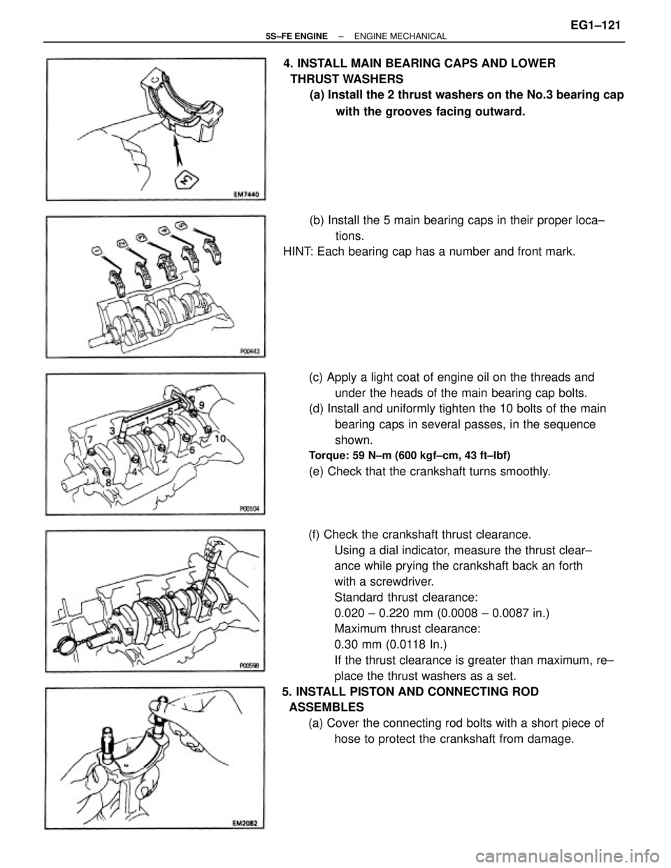
(f) Check the crankshaft thrust clearance.
Using a dial indicator, measure the thrust clear±
ance while prying the crankshaft back an forth
with a screwdriver.
Standard thrust clearance:
0.020 ± 0.220 mm (0.0008 ± 0.0087 in.)
Maximum thrust clearance:
0.30 mm (0.0118 In.)
If the thrust clearance is greater than maximum, re±
place the thrust washers as a set.
5. INSTALL PISTON AND CONNECTING ROD
ASSEMBLES
(a) Cover the connecting rod bolts with a short piece of
hose to protect the crankshaft from damage. (c) Apply a light coat of engine oil on the threads and
under the heads of the main bearing cap bolts.
(d) Install and uniformly tighten the 10 bolts of the main
bearing caps in several passes, in the sequence
shown.
Torque: 59 N±m (600 kgf±cm, 43 ft±lbf)
(e) Check that the crankshaft turns smoothly. 4. INSTALL MAIN BEARING CAPS AND LOWER
THRUST WASHERS
(a) Install the 2 thrust washers on the No.3 bearing cap
with the grooves facing outward.
(b) Install the 5 main bearing caps in their proper loca±
tions.
HINT: Each bearing cap has a number and front mark.
± 5S±FE ENGINEENGINE MECHANICALEG1±121
Page 204 of 4770
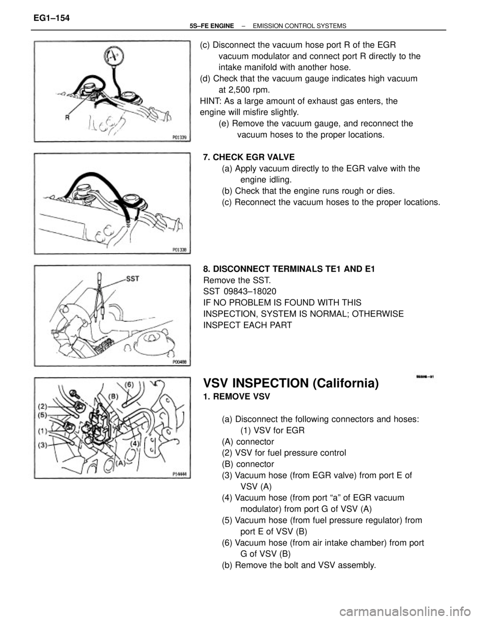
VSV INSPECTION (California)
1. REMOVE VSV
(a) Disconnect the following connectors and hoses:
(1) VSV for EGR
(A) connector
(2) VSV for fuel pressure control
(B) connector
(3) Vacuum hose (from EGR valve) from port E of
VSV (A)
(4) Vacuum hose (from port ªaº of EGR vacuum
modulator) from port G of VSV (A)
(5) Vacuum hose (from fuel pressure regulator) from
port E of VSV (B)
(6) Vacuum hose (from air intake chamber) from port
G of VSV (B)
(b) Remove the bolt and VSV assembly. (c) Disconnect the vacuum hose port R of the EGR
vacuum modulator and connect port R directly to the
intake manifold with another hose.
(d) Check that the vacuum gauge indicates high vacuum
at 2,500 rpm.
HINT: As a large amount of exhaust gas enters, the
engine will misfire slightly.
(e) Remove the vacuum gauge, and reconnect the
vacuum hoses to the proper locations.
8. DISCONNECT TERMINALS TE1 AND E1
Remove the SST.
SST 09843±18020
IF NO PROBLEM IS FOUND WITH THIS
INSPECTION, SYSTEM IS NORMAL; OTHERWISE
INSPECT EACH PART 7. CHECK EGR VALVE
(a) Apply vacuum directly to the EGR valve with the
engine idling.
(b) Check that the engine runs rough or dies.
(c) Reconnect the vacuum hoses to the proper locations.
± 5S±FE ENGINEEMISSION CONTROL SYSTEMSEG1±154
Page 222 of 4770
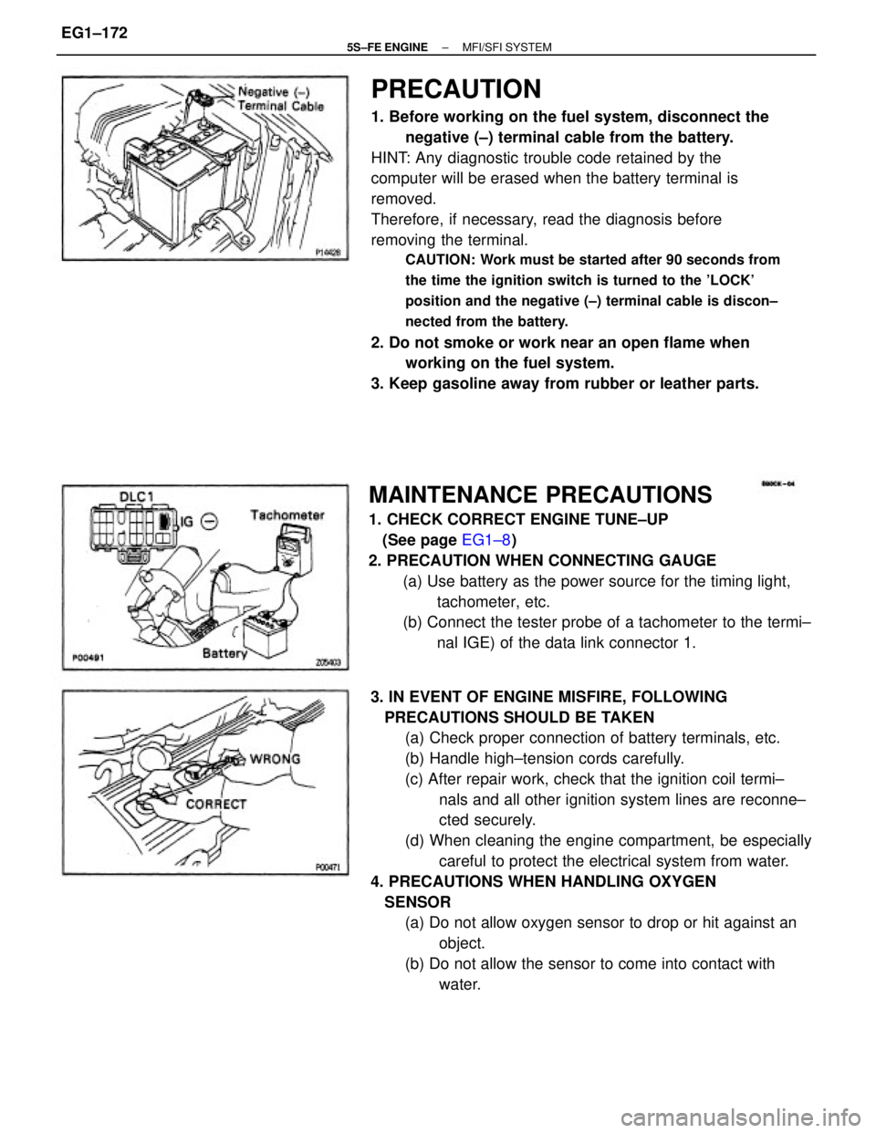
PRECAUTION
1. Before working on the fuel system, disconnect the
negative (±) terminal cable from the battery.
HINT: Any diagnostic trouble code retained by the
computer will be erased when the battery terminal is
removed.
Therefore, if necessary, read the diagnosis before
removing the terminal.
CAUTION: Work must be started after 90 seconds from
the time the ignition switch is turned to the 'LOCK'
position and the negative (±) terminal cable is discon±
nected from the battery.
2. Do not smoke or work near an open flame when
working on the fuel system.
3. Keep gasoline away from rubber or leather parts.
3. IN EVENT OF ENGINE MISFIRE, FOLLOWING
PRECAUTIONS SHOULD BE TAKEN
(a) Check proper connection of battery terminals, etc.
(b) Handle high±tension cords carefully.
(c) After repair work, check that the ignition coil termi±
nals and all other ignition system lines are reconne±
cted securely.
(d) When cleaning the engine compartment, be especially
careful to protect the electrical system from water.
4. PRECAUTIONS WHEN HANDLING OXYGEN
SENSOR
(a) Do not allow oxygen sensor to drop or hit against an
object.
(b) Do not allow the sensor to come into contact with
water.
MAINTENANCE PRECAUTIONS
1. CHECK CORRECT ENGINE TUNE±UP
(See page EG1±8)
2. PRECAUTION WHEN CONNECTING GAUGE
(a) Use battery as the power source for the timing light,
tachometer, etc.
(b) Connect the tester probe of a tachometer to the termi±
nal IGE) of the data link connector 1.
± 5S±FE ENGINEMFI/SFI SYSTEMEG1±172
Page 223 of 4770
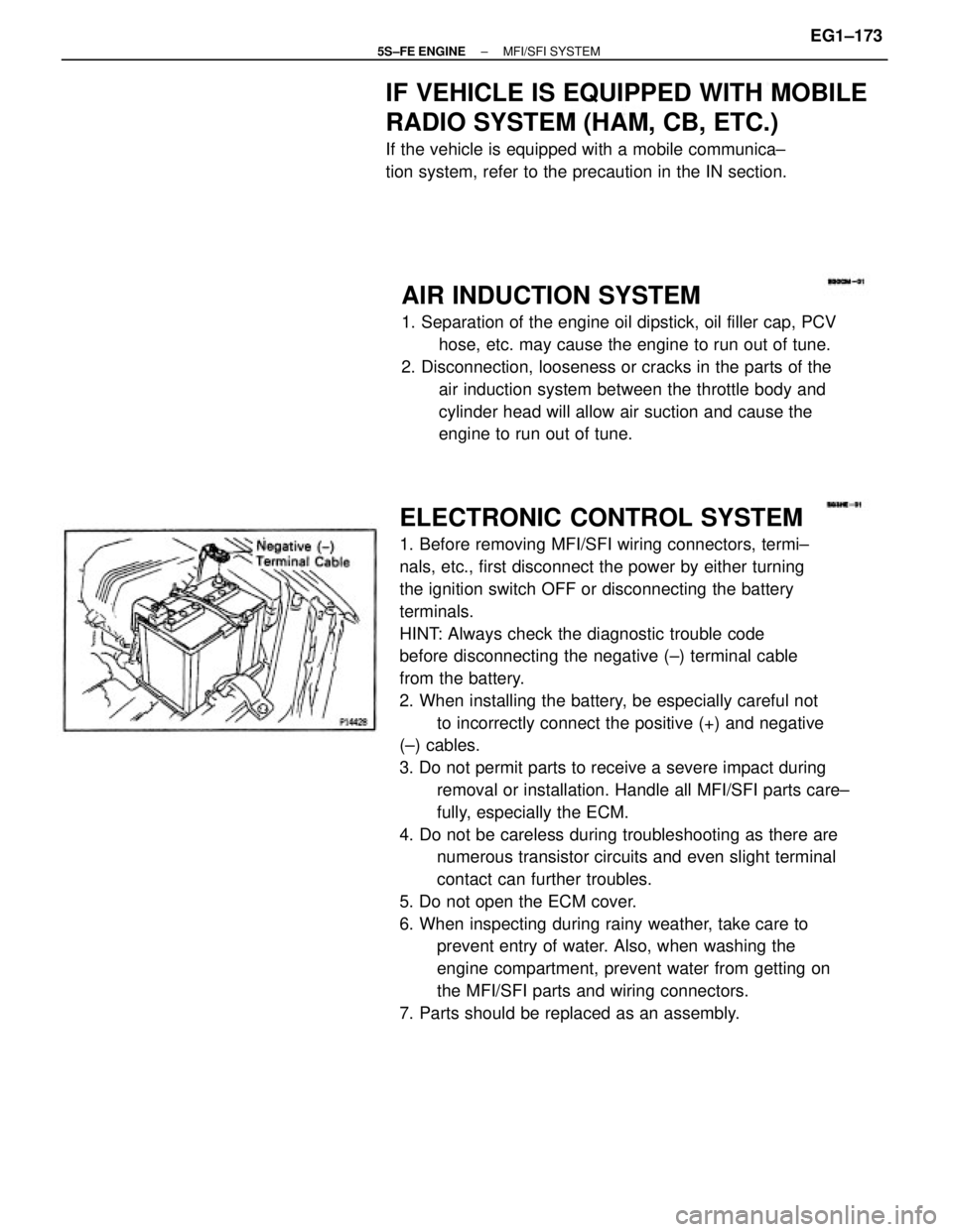
ELECTRONIC CONTROL SYSTEM
1. Before removing MFI/SFI wiring connectors, termi±
nals, etc., first disconnect the power by either turning
the ignition switch OFF or disconnecting the battery
terminals.
HINT: Always check the diagnostic trouble code
before disconnecting the negative (±) terminal cable
from the battery.
2. When installing the battery, be especially careful not
to incorrectly connect the positive (+) and negative
(±) cables.
3. Do not permit parts to receive a severe impact during
removal or installation. Handle all MFI/SFI parts care±
fully, especially the ECM.
4. Do not be careless during troubleshooting as there are
numerous transistor circuits and even slight terminal
contact can further troubles.
5. Do not open the ECM cover.
6. When inspecting during rainy weather, take care to
prevent entry of water. Also, when washing the
engine compartment, prevent water from getting on
the MFI/SFI parts and wiring connectors.
7. Parts should be replaced as an assembly.
AIR INDUCTION SYSTEM
1. Separation of the engine oil dipstick, oil filler cap, PCV
hose, etc. may cause the engine to run out of tune.
2. Disconnection, looseness or cracks in the parts of the
air induction system between the throttle body and
cylinder head will allow air suction and cause the
engine to run out of tune.
IF VEHICLE IS EQUIPPED WITH MOBILE
RADIO SYSTEM (HAM, CB, ETC.)
If the vehicle is equipped with a mobile communica±
tion system, refer to the precaution in the IN section.
± 5S±FE ENGINEMFI/SFI SYSTEMEG1±173