Page 1561 of 4770

AC0M4±02
N01143
W
N01150
± AIR CONDITIONINGCOMPRESSOR AND MAGNETIC CLUTCH
AC±39
2521 Author�: Date�:
COMPRESSOR AND MAGNETIC
CLUTCH
ON±VEHICLE INSPECTION
1. INSPECT COMPRESSOR FOR METALLIC SOUND
(a) Start engine.
(b) Check if there is a metallic sound from the compressor
when the A/C switch is on.
If metallic sound is heard, replace the compressor assembly.
2. INSPECT REFRIGERANT PRESSURE
See ºON±VEHICLE INSPECTIONº of AIR CONDITIONING
SYSTEM on page AC±3.
3. INSPECT COMPRESSOR LOCK SENSOR RESIS-
TANCE
(a) Disconnect the connector.
(b) Measure resistance between terminals 1 and 2.
Standard resistance: 65 ± 125 W at 20 °C (68 °F)
If resistance is not as specified, replace the compressor assem-
bly.
4. INSPECT VISUALLY FOR LEAKAGE OF REFRIGER-
ANT FROM SAFETY SEAL
Using a gas leak detector, check for leakage of refrigerant.
If there is any leakage, replace the compressor assembly.
5. CHECK FOR LEAKAGE OF GREASE FROM CLUTCH
BEARING
6. CHECK FOR SIGNS OF OIL ON PRESSURE PLATE OR
ROTOR
7. INSPECT MAGNETIC CLUTCH BEARING FOR NOISE
(a) Start engine.
(b) Check for abnormal noise from near the compressor
when the A/C switch is OFF.
If abnormal noise is being emitted, replace the magnetic clutch.
8. INSPECT MAGNETIC CLUTCH OPERATION
(a) Disconnect the connector.
(b) Connect the positive (+) lead from the battery to terminal
4 and the negative (±) lead to the body ground.
(c) Check that the magnetic clutch is energized.
If operation is not as specified, replace the magnetic clutch.
Page 1621 of 4770

INTRODUCTIONGLOSSARY OF SAE AND TOYOTA TERMS ±
IN±6
GLOSSARY OF SAE AND TOYOTA TERMS
This glossary lists all SAE±J1930 terms and abbreviations used in this manual in compliance with SAE
recommendations, as well as their Toyota equivalents.
SAE
ABBREVIATIONSSAE TERMSTOYOTA TERMS
( )±±ABBREVIATIONS
A/CAir ConditioningAir Conditioner
ACLAir CleanerAir Cleaner
AIRSecondary Air InjectionAir Injection (AI)
APAccelerator Pedal±
B+Battery Positive Voltage+B, Battery Voltage
BAROBarometric Pressure±
CACCharge Air CoolerIntercooler
CARBCarburetorCarburetor
CFIContinuous Fuel Injection±
CKPCrankshaft PositionCrank Angle
CLClosed LoopClosed Loop
CMPCamshaft PositionCam Angle
CPPClutch Pedal Position±
CTOXContinuous Trap Oxidizer±
CTPClosed Throttle Position±
DFIDirect Fuel Injection (Diesel)Direct Injection (DI)
DIDistributor Ignition±
DLC1
DLC2
DLC3Data Link Connector 1
Data Link Connector 2
Data Link Connector 31: Check Connector
2: Toyota Diagnosis Communication Link (TDCL)
3: OBD@@@@@: [g 2] Diagnostic Connector
DTCDiagnostic Trouble CodeDiagnostic Code
DTMDiagnostic Test Mode±
ECLEngine Control Level±
ECMEngine Control ModuleEngine ECU (Electronic Control Unit)
ECTEngine Coolant TemperatureCoolant Temperature, Water Temperature (THW)
EEPROMElectrically Erasable Programmable Read Only
MemoryElectrically Erasable Programmable Read Only Memory
(EEPROM),
Erasable Programmable Read Only Memory(EPROM)
EFEEarly Fuel EvaporationCold Mixture Heater (CMH), Heat Control Valve (HCV)
EGRExhaust Gas RecirculationExhaust Gas Recirculation (EGR)
EIElectronic IgnitionToyota Distributorless Ignition (TDI)
EMEngine ModificationEngine Modification (EM)
EPROMErasable Programmable Read Only MemoryProgrammable Read Only Memory (PROM)
EVAPEvaporative EmissionEvaporative Emission Control (EVAP)
FCFan Control±
FEEPROMFlash Electrically Erasable Programmable
Read Only Memory±
FEPROMFlash Erasable Programmable Read Only Memory±
FFFlexible Fuel±
FPFuel PumpFuel Pump
GENGeneratorAlternator
GNDGroundGround (GND)
HO2SHeated Oxygen SensorHeated Oxygen Sensor (HO2S)
IN016±02
Page 1622 of 4770

IATIntake Air TemperatureIntake or Inlet Air Temperature
ICMIgnition Control Module±
IFIIndirect Fuel")
INTRODUCTIONGLOSSARY OF SAE AND TOYOTA TERMS ±
IN±7
IACIdle Air ControlIdle Speed Control (ISC)
IATIntake Air TemperatureIntake or Inlet Air Temperature
ICMIgnition Control Module±
IFIIndirect Fuel InjectionIndirect Injection
IFSInertia Fuel±Shutoff±
ISCIdle Speed Control±
KSKnock SensorKnock Sensor
MAFMass Air FlowAir Flow Meter
MAPManifold Absolute PressureManifold Pressure
Intake Vacuum
MCMixture Control
Electric Bleed Air Control Valve (EBCV)
Mixture Control Valve (MCV)
Electric Air Control Valve (EACV)
MDPManifold Differential Pressure±
MFIMultiport Fuel InjectionElectronic Fuel Injection (EFI)
MILMalfunction Indicator LampCheck Engine Light
MSTManifold Surface Temperature±
MVZManifold Vacuum Zone±
NVRAMNon±Volatile Random Access Memory±
O2SOxygen SensorOxygen Sensor, O2 Sensor (O2S)
OBDOn±Board DiagnosticOn±Board Diagnostic (OBD)
OCOxidation Catalytic ConverterOxidation Catalyst Converter (OC), CCo
OPOpen LoopOpen Loop
PAIRPulsed Secondary Air InjectionAir Suction (AS)
PCMPowertrain Control Module±
PNPPark/Neutral Position±
PROMProgrammable Read Only Memory±
PSPPower Steering Pressure±
PTOXPeriodic Trap OxidizerDiesel Particulate Filter (DPF)
Diesel Particulate Trap (DPT)
RAMRandom Access MemoryRandom Access Memory (RAM)
RMRelay Module±
ROMRead Only MemoryRead Only Memory (ROM)
RPMEngine SpeedEngine Speed
SCSuperchargerSupercharger
SCBSupercharger Bypass±
SFISequential Multiport Fuel InjectionElectronic Fuel Injection (EFI), Sequential Injection
SPLSmoke Puff Limiter±
SRIService Reminder Indicator±
SRTSystem Readiness Test±
STScan Tool±
TBThrottle BodyThrottle Body
TBIThrottle Body Fuel InjectionSingle Point Injection
Central Fuel Injection (Ci)
TCTurbochargerTurbocharger
TCCTorque Converter ClutchTorque Converter
TCMTransmission Control ModuleTransmission ECU (Electronic Control Unit)
TPThrottle PositionThrottle Position
TRTransmission Range±
Page 1623 of 4770
INTRODUCTIONGLOSSARY OF SAE AND TOYOTA TERMS ±
IN±8
TVVThermal Vacuum ValveBimetallic Vacuum Switching Valve (BVSV)
Thermostatic Vacuum Switching Valve (TVSV)
TWCThree±Way Catalytic ConverterThree±Way Catalyst (TWC)
CC
RO
TWC+OCThree±Way + Oxidation Catalytic ConverterCCR + CCo
VA FVolume Air FlowAir Flow Meter
VRVoltage RegulatorVoltage Regulator
VSSVehicle Speed SensorVehicle Speed Sensor (Read Switch Type)
WOTWide Open ThrottleFull Throttle
WU±OCWarm Up Oxidation Catalytic Converter±
WU±TWCWarm Up Three±Way Catalytic ConverterManifold Converter
3GRThird Gear±
4GRFourth Gear±
Page 1640 of 4770
AUTOMATIC TRANSAXLEOPERATION ±
AX±7
2. ELECTRONIC CONTROL SYSTEM
The electronic control system for controlling the shift timing and the operation of the lock±up clutch is
composed of the following 3 parts:
(a) Sensors: These sense the vehicle speed and throttle position and send this data to the ECM in the form
of electronic signals.
(b) ECM: This determines the shift and lock±up timing based upon the signals from the sensors.
(c) Actuators: Solenoid valves divert hydraulic pressure from one circuit of the hydraulic control unit to
another, thus controlling shifting and lock±up timing.
Page 1664 of 4770
AUTOMATIC TRANSAXLECOMPONENT PARTS REMOVAL ±
AX±31
13. REMOVE ROTOR SENSOR
14. REMOVE DRIVE PINION
(a) Using SST, remove the snap ring.
SST 09350±32014 (09351±32050)
(b) Install a brass bar into case hole to tap out the drive pin-
ion.
(c) Tap the drive pinion and remove the bearing cage from
the bore.
15. REMOVE BEARING CAGE FROM DRIVE PINION
16. REMOVE O±RING FROM BEARING CAGE
Page 1735 of 4770
AUTOMATIC TRANSAXLECOMPONENT PARTS INSTALLATION ±
AX±102
3. INSTALL SNAP RING INTO CASE
(a) Using SST, install the snap ring into the groove.
SST 09350±32014 (09351±32050)
(b) Slightly tap the drive pinion to fit the snap ring into the
groove.
4. INSTALL ROTOR SENSOR
Install the rotor sensor, facing the magnet outward.
5. INSTALL OIL SLINGER
Install the oil slinger, facing the lip outward.
6. INSTALL OUTER RACE
Using SST, drive the outer race into the case.
SST 09350±32014 (09351±32100, 09351±32140)
Page 1761 of 4770
Q00207
AX036±01
Q04678
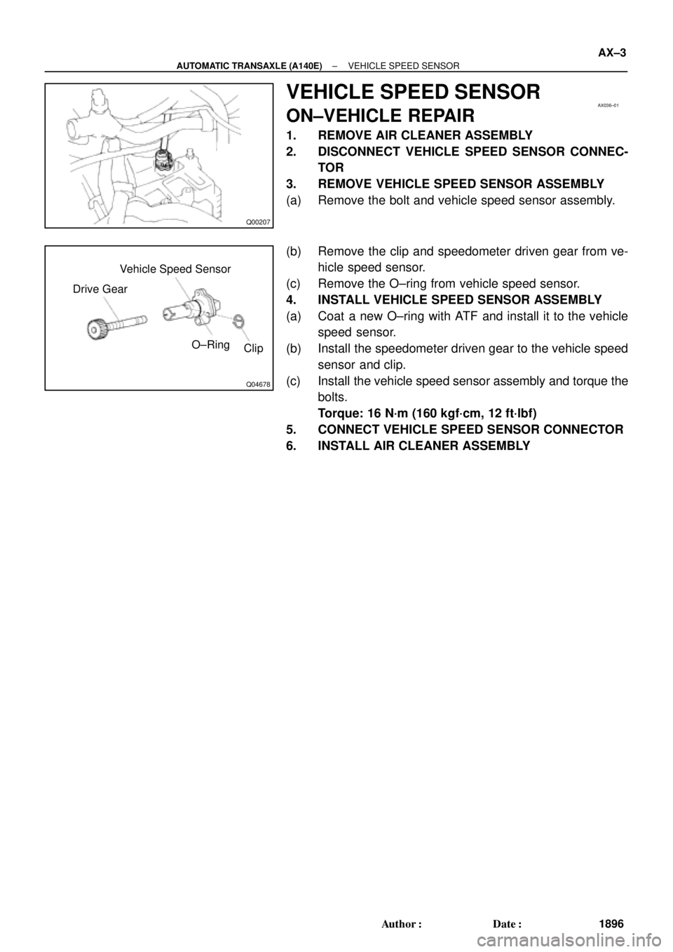
Drive GearVehicle Speed Sensor
O±Ring
Clip
± AUTOMATIC TRANSAXLE (A140E)VEHICLE SPEED SENSOR
AX±3
1896 Author�: Date�:
VEHICLE SPEED SENSOR
ON±VEHICLE REPAIR
1. REMOVE AIR CLEANER ASSEMBLY
2. DISCONNECT VEHICLE SPEED SENSOR CONNEC-
TOR
3. REMOVE VEHICLE SPEED SENSOR ASSEMBLY
(a) Remove the bolt and vehicle speed sensor assembly.
(b) Remove the clip and speedometer driven gear from ve-
hicle speed sensor.
(c) Remove the O±ring from vehicle speed sensor.
4. INSTALL VEHICLE SPEED SENSOR ASSEMBLY
(a) Coat a new O±ring with ATF and install it to the vehicle
speed sensor.
(b) Install the speedometer driven gear to the vehicle speed
sensor and clip.
(c) Install the vehicle speed sensor assembly and torque the
bolts.
Torque: 16 N´m (160 kgf´cm, 12 ft´lbf)
5. CONNECT VEHICLE SPEED SENSOR CONNECTOR
6. INSTALL AIR CLEANER ASSEMBLY

Thermostatic Vacuum Switching Valve (TVSV)
TWCThree±Way Catalytic ConverterThree�")

 Using SST, remove the snap ring.
SST 09350±32014 (09351±32050)
(b) Install a brass bar into c")
 Using SST, install the snap ring into the groove.
SST 09350±32014 (09351±32050)
(b) Slightly tap the dri")