Page 1777 of 4770
AUTOMATIC TRANSAXLE UNIT
AX±19
1912 Author�: Date�:
REMOVAL
1. REMOVE BATTERY
2. REMOVE AIR CLEANER ASSEMBLY
3. DISCONNECT THROTTLE")
AX03H±01
Q10055
Q00211
Q10056
Q10057
± AUTOMATIC TRANSAXLE (A140E)AUTOMATIC TRANSAXLE UNIT
AX±19
1912 Author�: Date�:
REMOVAL
1. REMOVE BATTERY
2. REMOVE AIR CLEANER ASSEMBLY
3. DISCONNECT THROTTLE CABLE
4. w/ CRUISE CONTROL:
REMOVE CRUISE CONTROL ACTUATOR
(a) Disconnect the connector.
(b) Remove the 3 bolts and disconnect cruise control actua-
tor with the bracket.
5. DISCONNECT OIL COOLER HOSE
6. DISCONNECT VEHICLE SPEED SENSOR CONNEC-
TOR
7. DISCONNECT PARK/NEUTRAL POSITION SWITCH
CONNECTOR
8. DISCONNECT SHIFT SOLENOID VALVE NO.1 AND
NO.2 CONNECTOR
9. DISCONNECT SHIFT SOLENOID VALVE SL CONNEC-
TOR
10. REMOVE 2 FRONT SIDE ENGINE MOUNTING BOLTS
Torque:
TMC made: 80 N´m (820 kgf´cm, 59 ft´lbf)
TMMK made:
Green color bolt: 66 N´m (670 kgf´cm, 48 ft´lbf)
Silver color bolt: 44 N´m (450 kgf´cm, 32 ft´lbf)
11. DISCONNECT 2 GROUND CABLES
12. REMOVE STARTER
(a) Disconnect the connector and remove the nut.
(b) Remove the 2 bolts, shift cable clamp and starter.
Torque: 39 N´m (400 kgf´cm, 29 ft´lbf)
13. REMOVE 3 TRANSAXLE±TO±ENGINE BOLTS
Torque: 66 N´m (670 kgf´cm, 48 ft´lbf)
Page 1791 of 4770

INTRODUCTIONGLOSSARY OF SAE AND TOYOTA TERMS ±
IN±6
GLOSSARY OF SAE AND TOYOTA TERMS
This glossary lists all SAE±J1930 terms and abbreviations used in this manual in compliance with SAE
recommendations, as well as their Toyota equivalents.
SAE
ABBREVIATIONSSAE TERMSTOYOTA TERMS
( )±±ABBREVIATIONS
A/CAir ConditioningAir Conditioner
ACLAir CleanerAir Cleaner
AIRSecondary Air InjectionAir Injection (AI)
APAccelerator Pedal±
B+Battery Positive Voltage+B, Battery Voltage
BAROBarometric Pressure±
CACCharge Air CoolerIntercooler
CARBCarburetorCarburetor
CFIContinuous Fuel Injection±
CKPCrankshaft PositionCrank Angle
CLClosed LoopClosed Loop
CMPCamshaft PositionCam Angle
CPPClutch Pedal Position±
CTOXContinuous Trap Oxidizer±
CTPClosed Throttle Position±
DFIDirect Fuel Injection (Diesel)Direct Injection (DI)
DIDistributor Ignition±
DLC1
DLC2
DLC3Data Link Connector 1
Data Link Connector 2
Data Link Connector 31: Check Connector
2: Toyota Diagnosis Communication Link (TDCL)
3: OBD@@@@@: [g 2] Diagnostic Connector
DTCDiagnostic Trouble CodeDiagnostic Code
DTMDiagnostic Test Mode±
ECLEngine Control Level±
ECMEngine Control ModuleEngine ECU (Electronic Control Unit)
ECTEngine Coolant TemperatureCoolant Temperature, Water Temperature (THW)
EEPROMElectrically Erasable Programmable Read Only
MemoryElectrically Erasable Programmable Read Only Memory
(EEPROM),
Erasable Programmable Read Only Memory(EPROM)
EFEEarly Fuel EvaporationCold Mixture Heater (CMH), Heat Control Valve (HCV)
EGRExhaust Gas RecirculationExhaust Gas Recirculation (EGR)
EIElectronic IgnitionToyota Distributorless Ignition (TDI)
EMEngine ModificationEngine Modification (EM)
EPROMErasable Programmable Read Only MemoryProgrammable Read Only Memory (PROM)
EVAPEvaporative EmissionEvaporative Emission Control (EVAP)
FCFan Control±
FEEPROMFlash Electrically Erasable Programmable
Read Only Memory±
FEPROMFlash Erasable Programmable Read Only Memory±
FFFlexible Fuel±
FPFuel PumpFuel Pump
GENGeneratorAlternator
GNDGroundGround (GND)
HO2SHeated Oxygen SensorHeated Oxygen Sensor (HO2S)
IN016±02
Page 1792 of 4770

IATIntake Air TemperatureIntake or Inlet Air Temperature
ICMIgnition Control Module±
IFIIndirect Fuel")
INTRODUCTIONGLOSSARY OF SAE AND TOYOTA TERMS ±
IN±7
IACIdle Air ControlIdle Speed Control (ISC)
IATIntake Air TemperatureIntake or Inlet Air Temperature
ICMIgnition Control Module±
IFIIndirect Fuel InjectionIndirect Injection
IFSInertia Fuel±Shutoff±
ISCIdle Speed Control±
KSKnock SensorKnock Sensor
MAFMass Air FlowAir Flow Meter
MAPManifold Absolute PressureManifold Pressure
Intake Vacuum
MCMixture Control
Electric Bleed Air Control Valve (EBCV)
Mixture Control Valve (MCV)
Electric Air Control Valve (EACV)
MDPManifold Differential Pressure±
MFIMultiport Fuel InjectionElectronic Fuel Injection (EFI)
MILMalfunction Indicator LampCheck Engine Light
MSTManifold Surface Temperature±
MVZManifold Vacuum Zone±
NVRAMNon±Volatile Random Access Memory±
O2SOxygen SensorOxygen Sensor, O2 Sensor (O2S)
OBDOn±Board DiagnosticOn±Board Diagnostic (OBD)
OCOxidation Catalytic ConverterOxidation Catalyst Converter (OC), CCo
OPOpen LoopOpen Loop
PAIRPulsed Secondary Air InjectionAir Suction (AS)
PCMPowertrain Control Module±
PNPPark/Neutral Position±
PROMProgrammable Read Only Memory±
PSPPower Steering Pressure±
PTOXPeriodic Trap OxidizerDiesel Particulate Filter (DPF)
Diesel Particulate Trap (DPT)
RAMRandom Access MemoryRandom Access Memory (RAM)
RMRelay Module±
ROMRead Only MemoryRead Only Memory (ROM)
RPMEngine SpeedEngine Speed
SCSuperchargerSupercharger
SCBSupercharger Bypass±
SFISequential Multiport Fuel InjectionElectronic Fuel Injection (EFI), Sequential Injection
SPLSmoke Puff Limiter±
SRIService Reminder Indicator±
SRTSystem Readiness Test±
STScan Tool±
TBThrottle BodyThrottle Body
TBIThrottle Body Fuel InjectionSingle Point Injection
Central Fuel Injection (Ci)
TCTurbochargerTurbocharger
TCCTorque Converter ClutchTorque Converter
TCMTransmission Control ModuleTransmission ECU (Electronic Control Unit)
TPThrottle PositionThrottle Position
TRTransmission Range±
Page 1793 of 4770
INTRODUCTIONGLOSSARY OF SAE AND TOYOTA TERMS ±
IN±8
TVVThermal Vacuum ValveBimetallic Vacuum Switching Valve (BVSV)
Thermostatic Vacuum Switching Valve (TVSV)
TWCThree±Way Catalytic ConverterThree±Way Catalyst (TWC)
CC
RO
TWC+OCThree±Way + Oxidation Catalytic ConverterCCR + CCo
VA FVolume Air FlowAir Flow Meter
VRVoltage RegulatorVoltage Regulator
VSSVehicle Speed SensorVehicle Speed Sensor (Read Switch Type)
WOTWide Open ThrottleFull Throttle
WU±OCWarm Up Oxidation Catalytic Converter±
WU±TWCWarm Up Three±Way Catalytic ConverterManifold Converter
3GRThird Gear±
4GRFourth Gear±
Page 1810 of 4770
AUTOMATIC TRANSAXLECOMPONENT PARTS REMOVAL ±
AX±14
5. REMOVE T/M REVOLUTION SENSOR
(a) Remove the bolt and T/M revolution sensor.
(b) Remove the O±ring from the T/M revolution sensor.
6. REMOVE TRANSAXLE CASE UPPER COVER
7. REMOVE OIL PAN AND GASKET
(a) Remove the 17 bolts.
(b) Remove the oil pan by lifting transaxle case.
NOTICE: Do not turn the transaxle over as this will contami-
nate the valve body with the foreign materials in the bottom
of the oil pan.
(c) Place the transaxle on wooden blocks to prevent damage
to the oil pipe bracket.
8. EXHAUST PARTICLES IN PAN
Remove the magnet and use it to collect any steel chips.
Lock carefully at the chips and particles in the oil pan and
on magnet to anticipate what type of wear you will find in
the transaxle.
�Steel (magnetic): bearing, gear and plate wear
�Brass (non±magnetic): bushing wear
9. REMOVE OIL PIPE BRACKET AND STRAINER
Page 1920 of 4770
AUTOMATIC TRANSAXLECOMPONENT PARTS INSTALLATION ±
AX±124
12. INSTALL MAGNETS IN PLACE
NOTICE: Make sure that the magnets do not interfere with
the oil pipes.
13. INSTALL OIL PAN WITH NEW GASKET
(a) Install a new gasket and oil pan.
(b) Install and torque the 17 bolts.
Torque: 4.9 N´m (50 kgf´cm, 43 in.´lbf)
14. INSTALL THROTTLE CABLE RETAINING PLATE
15. INSTALL TRANSAXLE UPPER COVER
16. INSTALL T/M REVOLUTION SENSOR
(a) Install a new O±ring to the T/M revolution sensor.
(b) Install the T/M revolution sensor with the bolt.
Page 1931 of 4770
Q05725
AX03N±01
Q04678
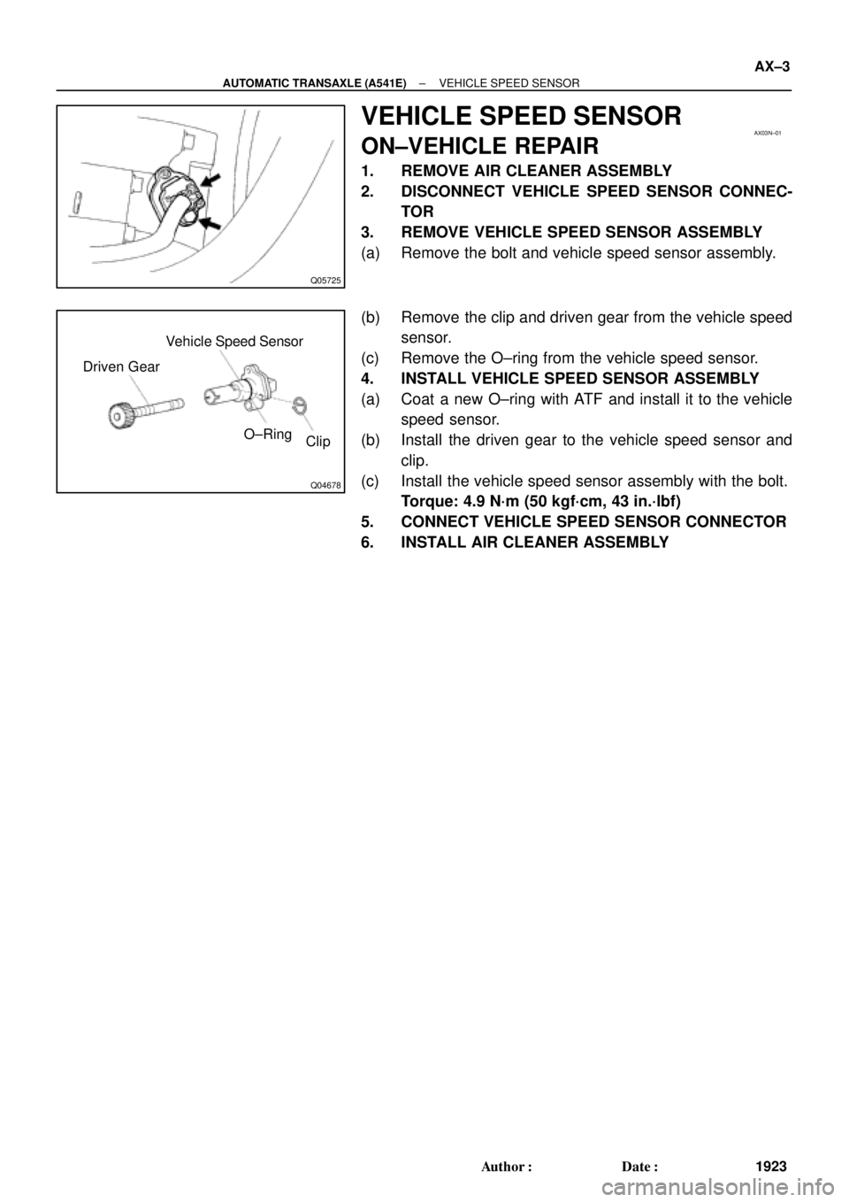
Clip O±Ring Driven GearVehicle Speed Sensor
± AUTOMATIC TRANSAXLE (A541E)VEHICLE SPEED SENSOR
AX±3
1923 Author�: Date�:
VEHICLE SPEED SENSOR
ON±VEHICLE REPAIR
1. REMOVE AIR CLEANER ASSEMBLY
2. DISCONNECT VEHICLE SPEED SENSOR CONNEC-
TOR
3. REMOVE VEHICLE SPEED SENSOR ASSEMBLY
(a) Remove the bolt and vehicle speed sensor assembly.
(b) Remove the clip and driven gear from the vehicle speed
sensor.
(c) Remove the O±ring from the vehicle speed sensor.
4. INSTALL VEHICLE SPEED SENSOR ASSEMBLY
(a) Coat a new O±ring with ATF and install it to the vehicle
speed sensor.
(b) Install the driven gear to the vehicle speed sensor and
clip.
(c) Install the vehicle speed sensor assembly with the bolt.
Torque: 4.9 N´m (50 kgf´cm, 43 in.´lbf)
5. CONNECT VEHICLE SPEED SENSOR CONNECTOR
6. INSTALL AIR CLEANER ASSEMBLY
Page 1932 of 4770
Q05726
AX03O±01
Q04733
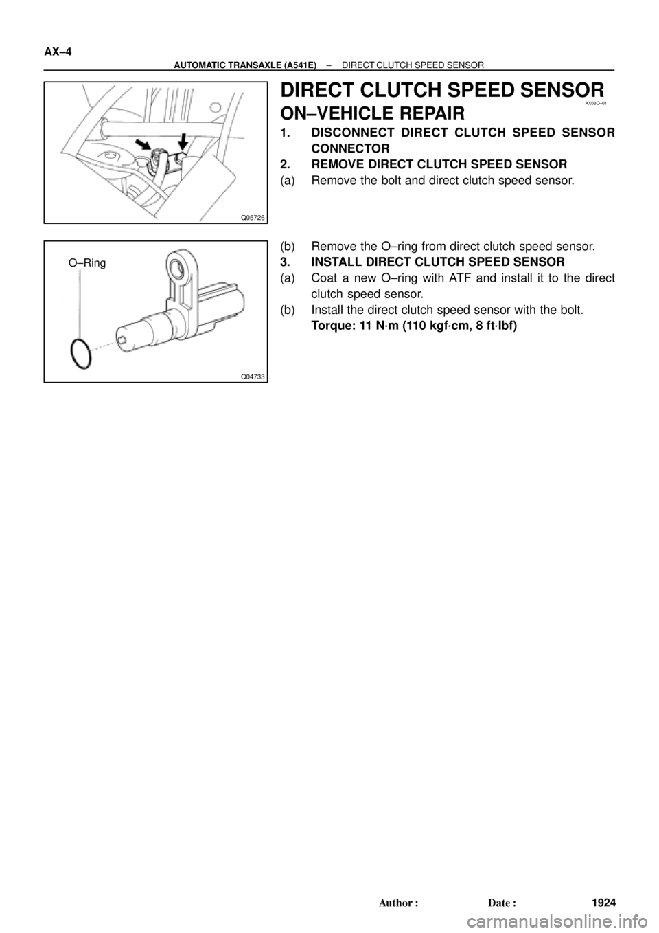
O±Ring AX±4
± AUTOMATIC TRANSAXLE (A541E)DIRECT CLUTCH SPEED SENSOR
1924 Author�: Date�:
DIRECT CLUTCH SPEED SENSOR
ON±VEHICLE REPAIR
1. DISCONNECT DIRECT CLUTCH SPEED SENSOR
CONNECTOR
2. REMOVE DIRECT CLUTCH SPEED SENSOR
(a) Remove the bolt and direct clutch speed sensor.
(b) Remove the O±ring from direct clutch speed sensor.
3. INSTALL DIRECT CLUTCH SPEED SENSOR
(a) Coat a new O±ring with ATF and install it to the direct
clutch speed sensor.
(b) Install the direct clutch speed sensor with the bolt.
Torque: 11 N´m (110 kgf´cm, 8 ft´lbf)

Thermostatic Vacuum Switching Valve (TVSV)
TWCThree±Way Catalytic ConverterThree�")
 Remove the bolt and T/M revolution sensor.
(b) Remove the O±ring from the T/M revolution sensor.
6. REMOVE TRA")
")