Page 2130 of 4770
BE0AE±02
Z19048
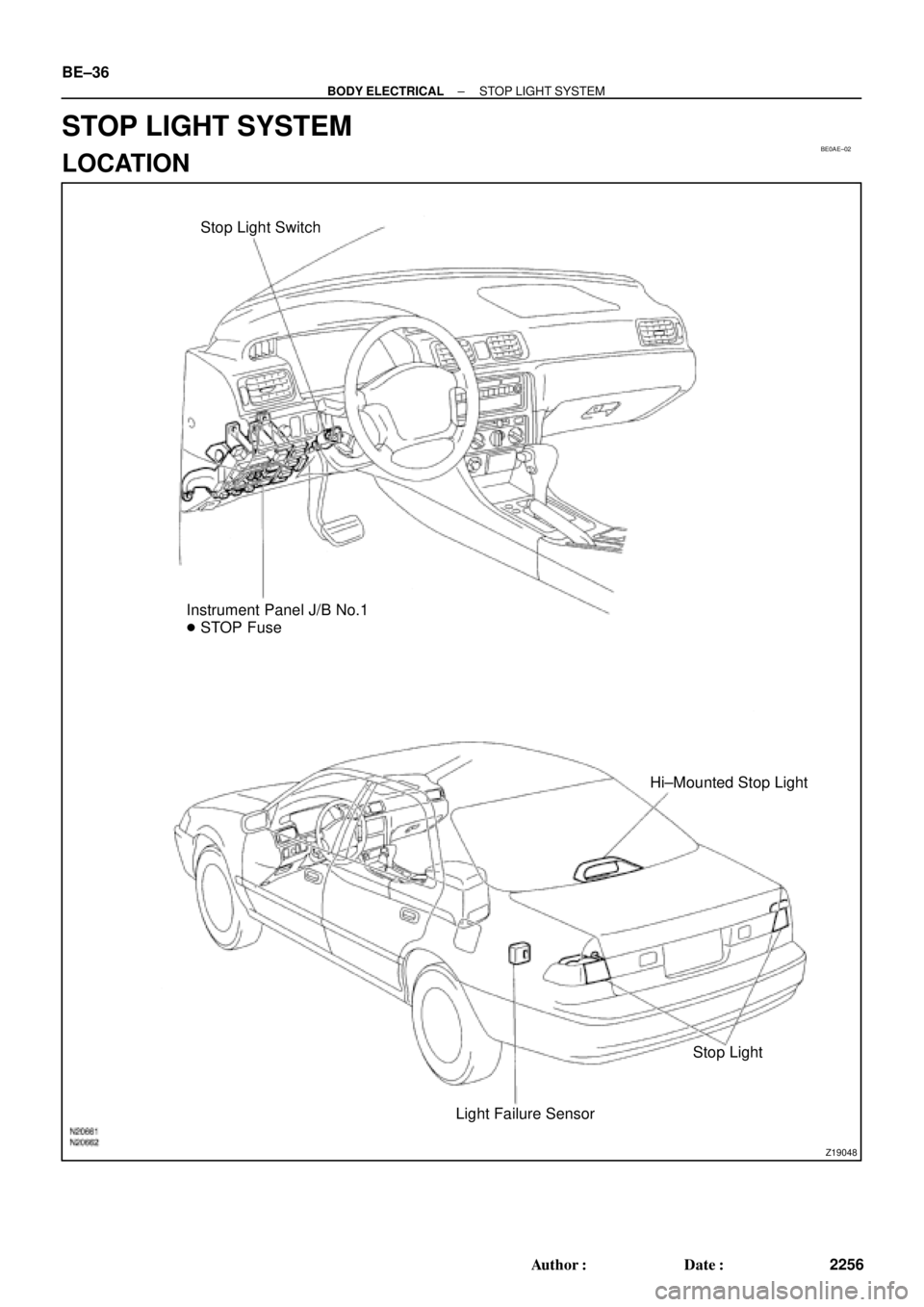
Stop Light Switch
Instrument Panel J/B No.1
� STOP Fuse
Hi±Mounted Stop Light
Stop Light
Light Failure Sensor BE±36
± BODY ELECTRICALSTOP LIGHT SYSTEM
2256 Author�: Date�:
STOP LIGHT SYSTEM
LOCATION
Page 2139 of 4770
Z19055
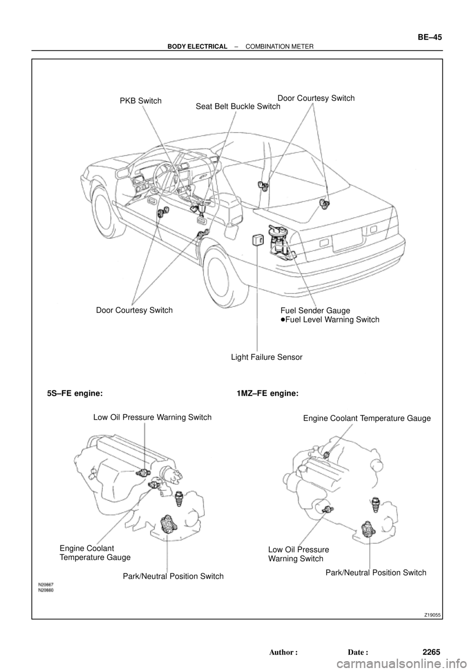
PKB Switch
Seat Belt Buckle SwitchDoor Courtesy Switch
Door Courtesy Switch
Light Failure SensorFuel Sender Gauge
�Fuel Level Warning Switch
5S±FE engine: 1MZ±FE engine:
Low Oil Pressure Warning Switch
Engine Coolant Temperature Gauge
Engine Coolant
Temperature Gauge
Park/Neutral Position SwitchLow Oil Pressure
Warning Switch
Park/Neutral Position Switch
± BODY ELECTRICALCOMBINATION METER
BE±45
2265 Author�: Date�:
Page 2140 of 4770

BE0AJ±03
Z18937
Connector ºAº Connector ºBº Connector ºCº
Connector ºAº
Connector ºBº
Connector ºCº
J±13±1±A J±16±1 J±13±1
1 2 3 4 5 6 7 8 9 10 11 12 1314 15 16 1 234 56 78 910111213 1 23456 78910111213
C7
C5
A2 B3
A1
C8
B15
C6
B6
A4
C4
B5
C10 B14
A13
B2
C1
B1
C9
A6
A11
A7
A10
A8
A9
C13
B8
B11
B12A5
C11
B4
B16 C2
A12
A3
B7
C3
C12
B9
B10
B13 F
E
T
S
ODOMETER
Fuel Level Warning
Seat Belt Warning
ABS Warning
Low Oil Pressure Warning
Cruise Control Indicator
Malfunction Indicator
O/D OFF Indicator
Light Failure Warning
Brake Warning
SLIP Indicator
TRAC Indicator
Washer Level Warning
Discharge Warning
Right Turn Indicator
Left Turn Indicator
Security Indicator
L
2
D
N
R
P
Illumination
Hi±Beam Indicator
Open Door Warning
SRS Warning
: Fuel Gauge
: Engine Coolant Temperature Gauge
: Tachometer
: Speedometer
No.
A
B
C1
2
3
4
5
6
7 8
9
10
11
12 13
14
15
16
2 3
4
5
6
7 8
9
10
11 12
131
2
3
4 5
6
7
8
9
10
11
12
13
F
E
T
SEngine coolant temperature sender gauge
Ground
Light failure sensor
Integration relay
Traction ECU
Park/neutral position switch (A/T)
O/D OFF switch (A/T)
IGN fuse
Turn signal switch
ST relay
Fuel sender gauge
Generator
Oil pressure switch
Fuel sender gauge
Parking brake switch and brake fluid level warning switch
Headlight dimmer switch
Headlight dimmer switch
Door courtesy switch
DOME fuse
ECU±B fuse
Airbag sensor assembly
ECM
No.1 Vehicle speed sensor Ground
Turn signal switch ECM
Traction ECU
ABS ECU
Ground No.1 Vehicle speed sensor
GAUGE fuse
Igniter
Security ECU
Cruise control ECU
Washer fluid level warning switch
Light control rheostat
TAIL fuse Park/neutral position switch (A/T) Park/neutral position switch (A/T) Park/neutral position switch (A/T) Park/neutral position switch (A/T)
Park/neutral position switch (A/T)Wire Harness Side
Bulb Check
Relay
N20107 N201081
BE±46
± BODY ELECTRICALCOMBINATION METER
2266 Author�: Date�:
CIRCUIT
Page 2141 of 4770

BE0AK±03
N02332
1
2 3
± BODY ELECTRICALCOMBINATION METER
BE±47
2267 Author�: Date�:
INSPECTION
1. INSPECT SPEEDOMETER ON±VEHICLE
Using a speedometer tester, inspect the speedometer for allow-
able indication error and check the operation of the odometer.
HINT:
Tire wear and tire over or under inflation will increase the indica-
tion error.
If error is excessive, replace the speedometer.
USA (mph)CANADA (km/h)
Standard indication Allowable rangeStandard indication Allowable range
20 18 ± 24 20 17 ± 24
40 38 ± 44 40 38 ± 46
60 56 ± 66 60 57.5 ± 67
80 78 ± 88 80 77 ± 88
100 98 ± 110 100 96 ± 109
120 118 ± 132 120 115 ± 130
140 134 ± 151.5
160 153 ± 173
2. INSPECT VEHICLE SPEED SENSOR OPERATION
(a) Connect the positive (+) lead from the battery to terminal
1 and negative (±) lead to terminal 2.
(b) Connect the positive (+) lead from the tester to terminal
3 and the negative (±) lead to terminal 2.
(c) Rotate the shaft.
(d) Check that there is voltage change from approx. 0 V to
11 V or more between terminals 2 and 3.
HINT:
The voltage change should be performed 4 times for every rev-
olution of the speed sensor shaft.
If operation is not as specified, replace the sensor.
3. INSPECT TACHOMETER ON±VEHICLE
(a) Connect a tune±up test tachometer, and start the engine.
NOTICE:
�Reversing the connection of the tachometer will dam-
age the transistors and diodes inside.
�When removing or installing the tachometer, be care-
ful not to drop or subject it to heavy shocks.
Page 2289 of 4770
BR0BQ±03
W03273
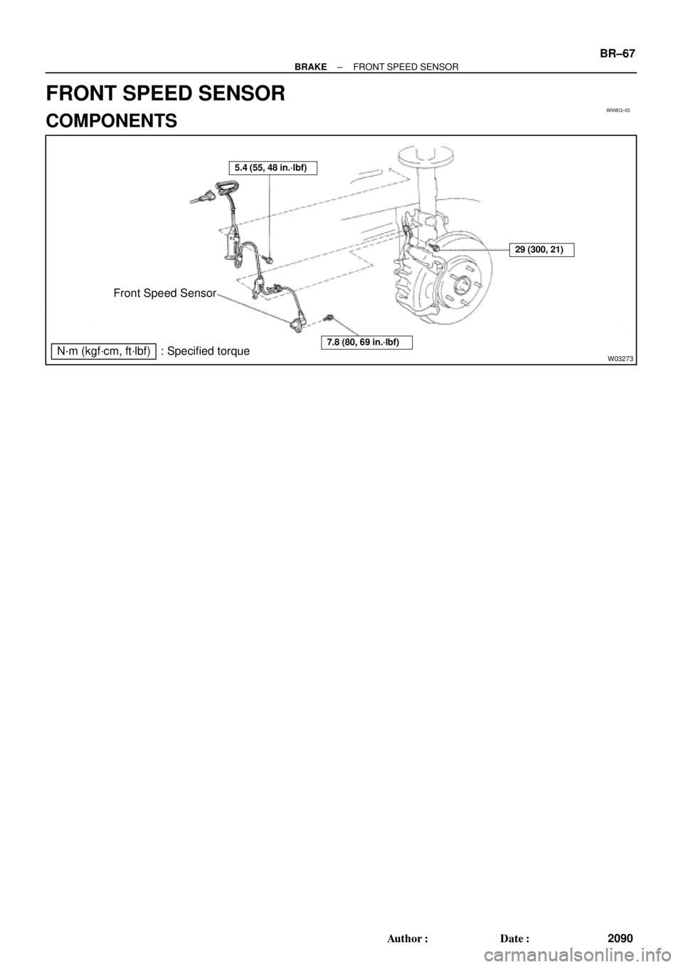
Front Speed Sensor
N´m (kgf´cm, ft´lbf) : Specified torque
5.4 (55, 48 in.´lbf)
7.8 (80, 69 in.´lbf)
29 (300, 21)
± BRAKEFRONT SPEED SENSOR
BR±67
2090 Author�: Date�:
FRONT SPEED SENSOR
COMPONENTS
Page 2290 of 4770
BR0BR±03
R00327
W04507
BR±68
± BRAKEFRONT SPEED SENSOR
2091 Author�: Date�:
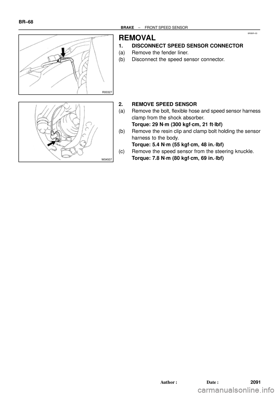
REMOVAL
1. DISCONNECT SPEED SENSOR CONNECTOR
(a) Remove the fender liner.
(b) Disconnect the speed sensor connector.
2. REMOVE SPEED SENSOR
(a) Remove the bolt, flexible hose and speed sensor harness
clamp from the shock absorber.
Torque: 29 N´m (300 kgf´cm, 21 ft´lbf)
(b) Remove the resin clip and clamp bolt holding the sensor
harness to the body.
Torque: 5.4 N´m (55 kgf´cm, 48 in.´lbf)
(c) Remove the speed sensor from the steering knuckle.
Torque: 7.8 N´m (80 kgf´cm, 69 in.´lbf)
Page 2291 of 4770
BR0BS±02
± BRAKEFRONT SPEED SENSOR
BR±69
2092 Author�: Date�:
INSTALLATION
Installation is in the reverse order of removal (See pageBR±68).
HINT:
After installation, check the speed sensor signal (See page DI±493, DI±539).
Page 2292 of 4770
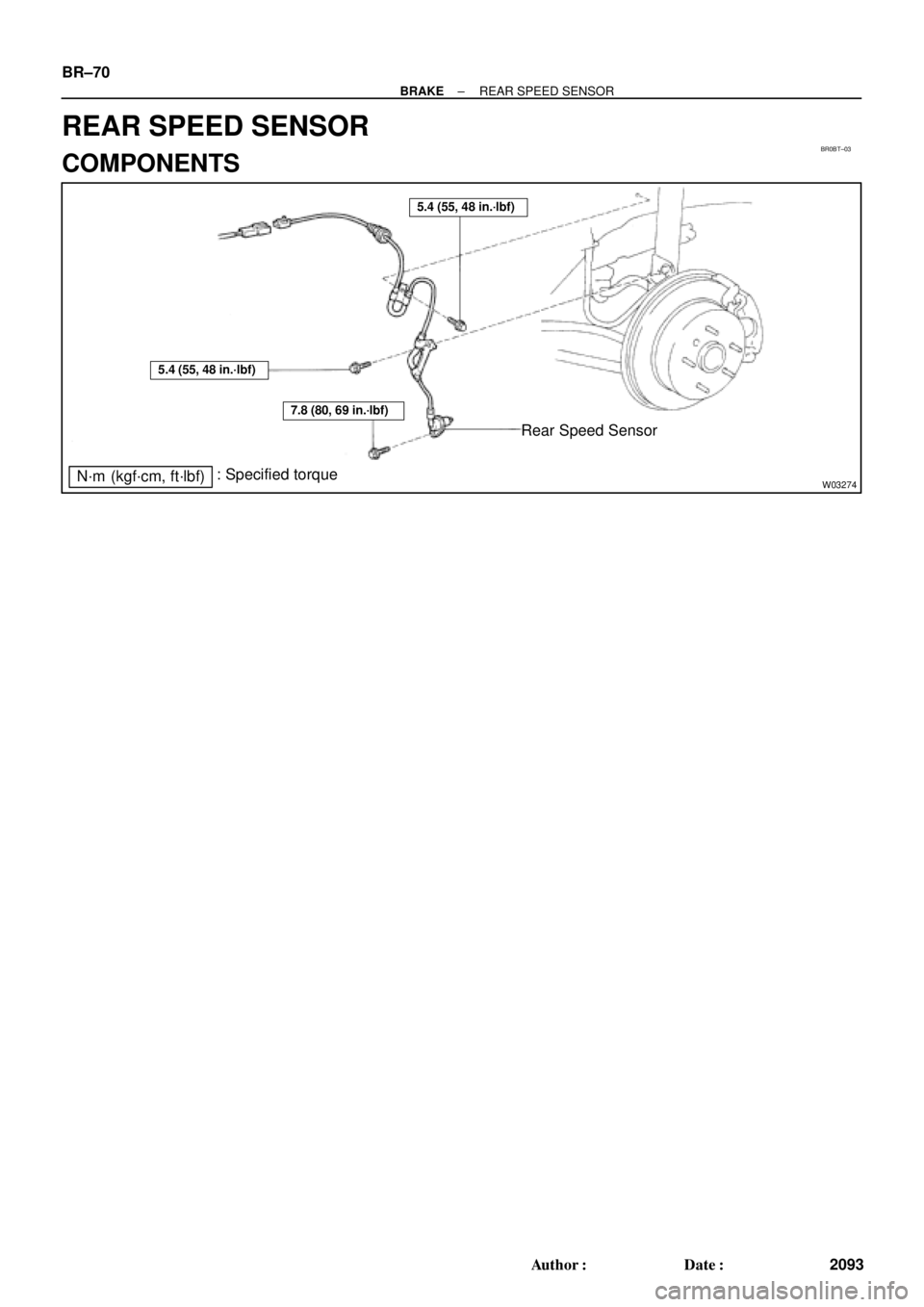
BR0BT±03
W03274
Rear Speed Sensor
N´m (kgf´cm, ft´lbf): Specified torque
5.4 (55, 48 in.´lbf)
7.8 (80, 69 in.´lbf)
5.4 (55, 48 in.´lbf)
BR±70
± BRAKEREAR SPEED SENSOR
2093 Author�: Date�:
REAR SPEED SENSOR
COMPONENTS