Page 3308 of 4770
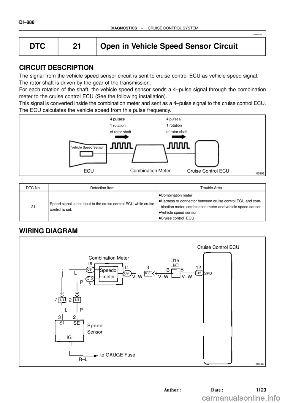
I00292
Vehicle Speed Sensor
ECUCombination Meter
Cruise Control ECU
4 pulses/
1 rotation
of rotor shaft4 pulses/
1 rotation
of rotor shaft
I00282
Cruise Control ECU
12
SPDV±W V±WB
BJ15
J/CIG3
3
V±W14
Combination Meter
15
6
Speedo
±meter
P L
IJ12IJ17
P
3L
2
SI
SE
IG+
1
R±Lto GAUGE Fuse
C15
C9 C9
C10
Speed
Sensor DI±888
± DIAGNOSTICSCRUISE CONTROL SYSTEM
1123 Author�: Date�:
DTC 21 Open in Vehicle Speed Sensor Circuit
CIRCUIT DESCRIPTION
The signal from the vehicle speed sensor circuit is sent to cruise control ECU as vehicle speed signal.
The rotor shaft is driven by the gear of the transmission.
For each rotation of the shaft, the vehicle speed sensor sends a 4±pulse signal through the combination
meter to the cruise control ECU (See the following installation).
This signal is converted inside the combination meter and sent as a 4±pulse signal to the cruise control ECU.
The ECU calculates the vehicle speed from this pulse frequency.
DTC No.Detection ItemTrouble Area
21Speed signal is not input to the cruise control ECU while cruise
control is set.
�Combination meter
�Harness or connector between cruise control ECU and com-
bination meter, combination meter and vehicle speed sensor
�Vehicle speed sensor
�Cruise control ECU
WIRING DIAGRAM
DI08P±12
Page 3321 of 4770
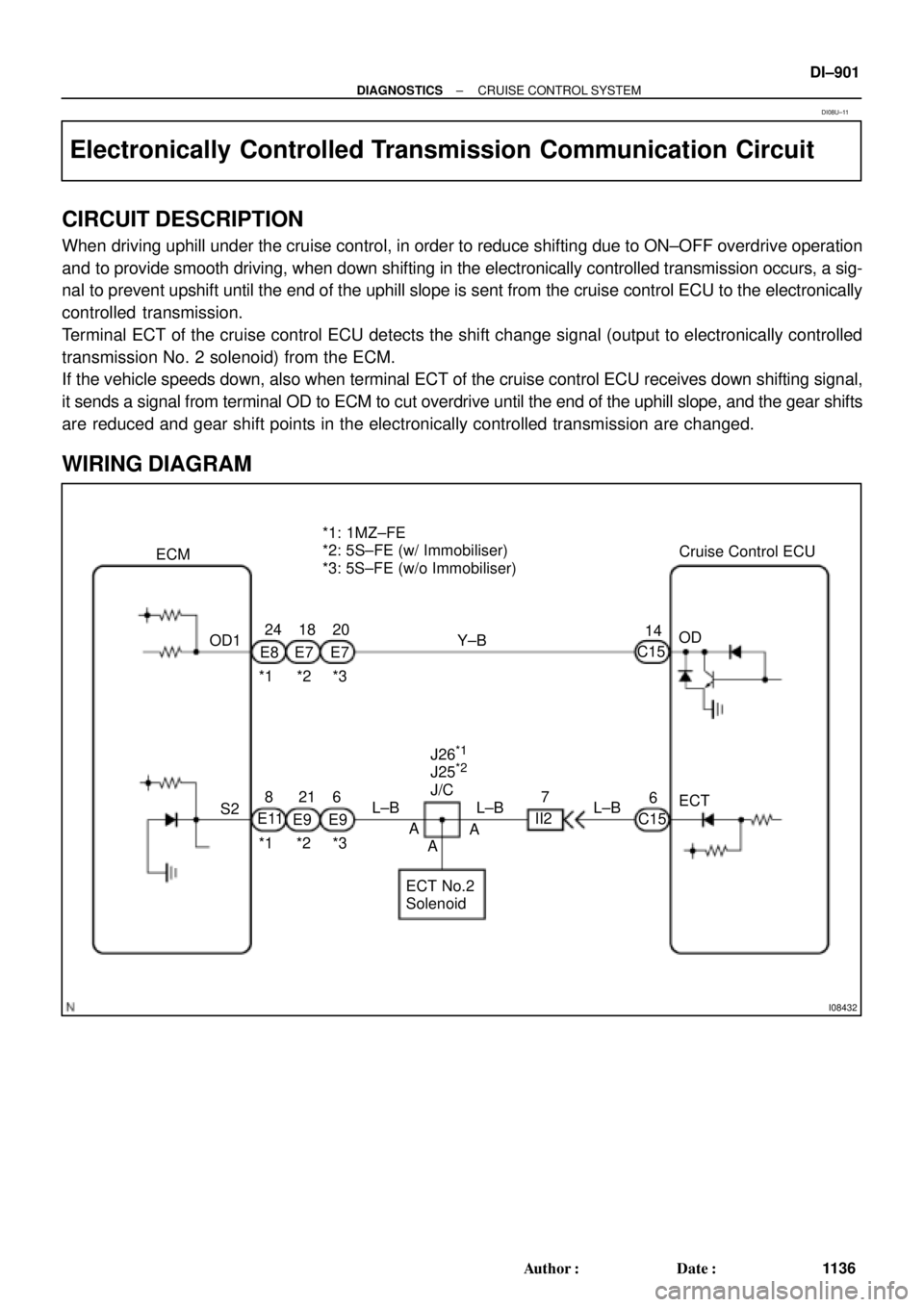
I08432
S2OD 14Cruise Control ECU *1: 1MZ±FE
*2: 5S±FE (w/ Immobiliser)
*3: 5S±FE (w/o Immobiliser)
ECT No.2
SolenoidECT C15
6
C15 Y±B
L±B ECM
24 18 20
E8 E7 E7
*1 *2 *3 OD1
8216
E11
E9 E9
*1 *2 *3L±B L±B7
II2 J26
*1
J25*2
J/C
A
AA
± DIAGNOSTICSCRUISE CONTROL SYSTEM
DI±901
1136 Author�: Date�:
Electronically Controlled Transmission Communication Circuit
CIRCUIT DESCRIPTION
When driving uphill under the cruise control, in order to reduce shifting due to ON±OFF overdrive operation
and to provide smooth driving, when down shifting in the electronically controlled transmission occurs, a sig-
nal to prevent upshift until the end of the uphill slope is sent from the cruise control ECU to the electronically
controlled transmission.
Terminal ECT of the cruise control ECU detects the shift change signal (output to electronically controlled
transmission No. 2 solenoid) from the ECM.
If the vehicle speeds down, also when terminal ECT of the cruise control ECU receives down shifting signal,
it sends a signal from terminal OD to ECM to cut overdrive until the end of the uphill slope, and the gear shifts
are reduced and gear shift points in the electronically controlled transmission are changed.
WIRING DIAGRAM
DI08U±11
Page 3322 of 4770
AB0119
I00143
I00174
ON
O/D
(±) (+)
DI±902
± DIAGNOSTICSCRUISE CONTROL SYSTEM
1137 Author�: Date�:
INSPECTION PROCEDURE
1 Check operation of overdrive.
PREPARATION:
Test drive after engine warms up.
CHECK:
Check that overdrive ON e OFF occurs by operation of OD switch ON±OFF.
NG Check and repair electronically controlled
transmission (See page DI±389).
OK
2 Check voltage between terminal OD of harness side connector of cruise control
ECU and body ground.
PREPARATION:
(a) Remove the ECU with connector still connected.
(b) Turn ignition switch ON.
(c) Disconnect the ECU connector.
CHECK:
Measure voltage between terminal OD of harness side connec-
tor of ECU and body ground.
OK:
Voltage: 10 ± 14 V
NG Go to step 5.
OK
Page 3323 of 4770
I00141
ECT
(±) (+)
± DIAGNOSTICSCRUISE CONTROL SYSTEM
DI±903
1138 Author�: Date�:
3 Check voltage between terminal ECT of cruise control ECU connector and body
ground (On test drive).
PREPARATION:
(a) Connect the ECU connector.
(b) Test drive after engine warms up.
CHECK:
Check voltage between terminal ECT of ECU connector and
body ground when OD switch is ON and OFF.
OK:
OD switch positionVoltage
ON8 ± 14 V
OFFBelow 0.5 V
OK Proceed to next circuit inspection shown on
problem symptoms table (See page DI±879).
NG
4 Check harness and connector between terminal ECT of cruise control ECU and
electronically controlled transmission solenoid (See page IN±31).
NG Repair or replace harness or connector.
OK
Check and replace cruise control ECU.
5 Check harness and connector between terminal OD of cruise control ECU and
terminal OD1 of ECM (See page IN±31).
NG Repair or replace harness or connector.
OK
Check and replace cruise control ECU
(See page IN±31).
Page 3393 of 4770
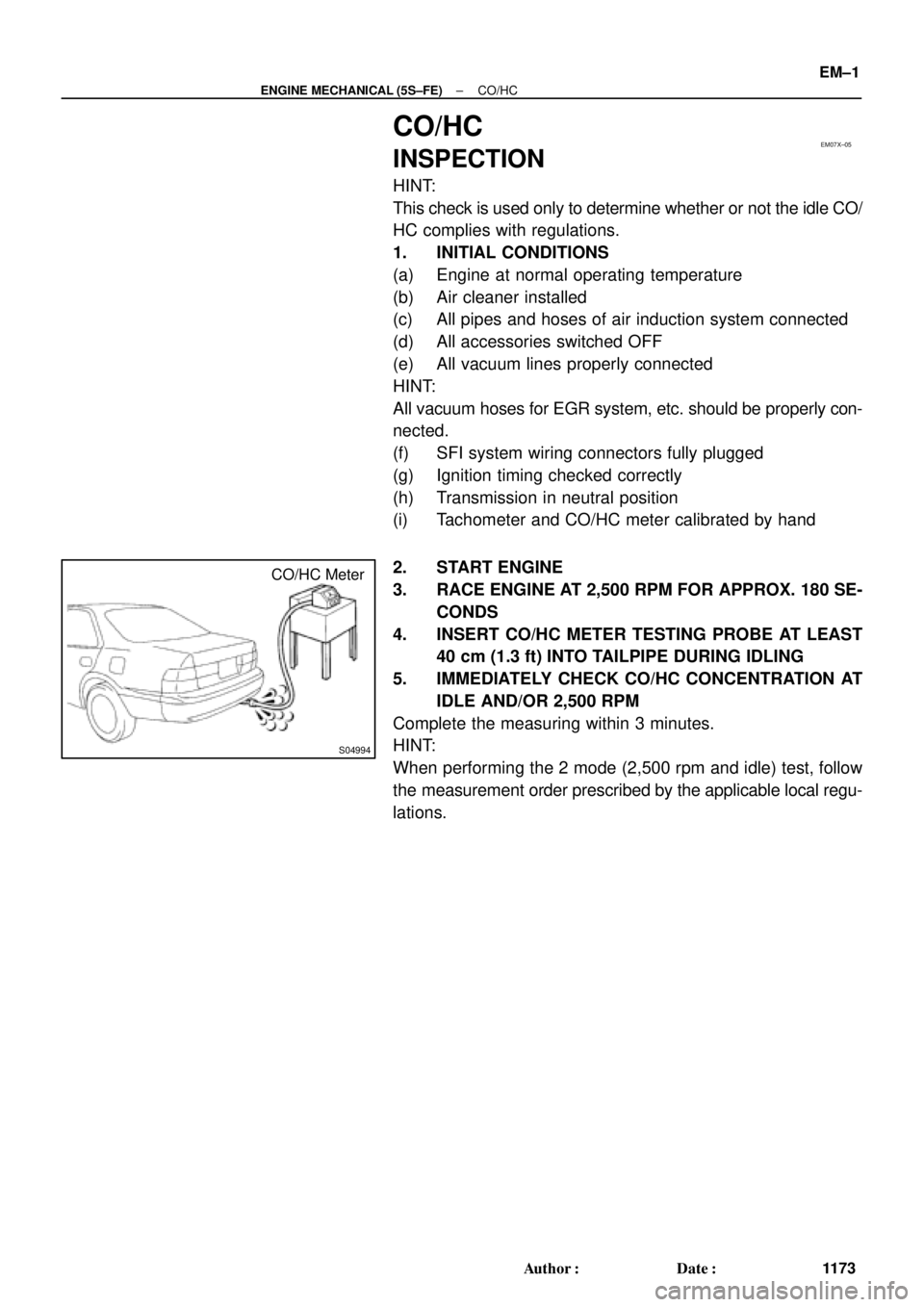
EM07X±05
S04994
CO/HC Meter
± ENGINE MECHANICAL (5S±FE)CO/HC
EM±1
1173 Author�: Date�:
CO/HC
INSPECTION
HINT:
This check is used only to determine whether or not the idle CO/
HC complies with regulations.
1. INITIAL CONDITIONS
(a) Engine at normal operating temperature
(b) Air cleaner installed
(c) All pipes and hoses of air induction system connected
(d) All accessories switched OFF
(e) All vacuum lines properly connected
HINT:
All vacuum hoses for EGR system, etc. should be properly con-
nected.
(f) SFI system wiring connectors fully plugged
(g) Ignition timing checked correctly
(h) Transmission in neutral position
(i) Tachometer and CO/HC meter calibrated by hand
2. START ENGINE
3. RACE ENGINE AT 2,500 RPM FOR APPROX. 180 SE-
CONDS
4. INSERT CO/HC METER TESTING PROBE AT LEAST
40 cm (1.3 ft) INTO TAILPIPE DURING IDLING
5. IMMEDIATELY CHECK CO/HC CONCENTRATION AT
IDLE AND/OR 2,500 RPM
Complete the measuring within 3 minutes.
HINT:
When performing the 2 mode (2,500 rpm and idle) test, follow
the measurement order prescribed by the applicable local regu-
lations.
Page 3401 of 4770
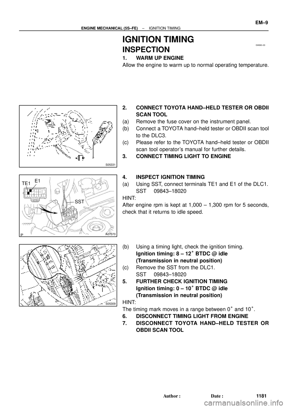
EM080±03
S05331
A07370
SST
E1
TE1
S05309
± ENGINE MECHANICAL (5S±FE)IGNITION TIMING
EM±9
1181 Author�: Date�:
IGNITION TIMING
INSPECTION
1. WARM UP ENGINE
Allow the engine to warm up to normal operating temperature.
2. CONNECT TOYOTA HAND±HELD TESTER OR OBDII
SCAN TOOL
(a) Remove the fuse cover on the instrument panel.
(b) Connect a TOYOTA hand±held tester or OBDII scan tool
to the DLC3.
(c) Please refer to the TOYOTA hand±held tester or OBDII
scan tool operator's manual for further details.
3. CONNECT TIMING LIGHT TO ENGINE
4. INSPECT IGNITION TIMING
(a) Using SST, connect terminals TE1 and E1 of the DLC1.
SST 09843±18020
HINT:
After engine rpm is kept at 1,000 ± 1,300 rpm for 5 seconds,
check that it returns to idle speed.
(b) Using a timing light, check the ignition timing.
Ignition timing: 8 ± 12° BTDC @ idle
(Transmission in neutral position)
(c) Remove the SST from the DLC1.
SST 09843±18020
5. FURTHER CHECK IGNITION TIMING
Ignition timing: 0 ± 10° BTDC @ idle
(Transmission in neutral position)
HINT:
The timing mark moves in a range between 0° and 10°.
6. DISCONNECT TIMING LIGHT FROM ENGINE
7. DISCONNECT TOYOTA HAND±HELD TESTER OR
OBDII SCAN TOOL
Page 3402 of 4770

EM081±05
S05331
EM±10
± ENGINE MECHANICAL (5S±FE)IDLE SPEED
1182 Author�: Date�:
IDLE SPEED
INSPECTION
1. INITIAL CONDITIONS
(a) Engine at normal operating temperature
(b) Air cleaner installed
(c) All pipes and hoses of air induction system connected
(d) All vacuum lines properly connected
(e) SFI system wiring connectors fully plugged
(f) All operating accessories switched OFF
(g) Ignition timing check correctly
(h) Transmission in neutral position
(i) Air conditioning switched OFF
2. CONNECT TOYOTA HAND±HELD TESTER OR OBDII
SCAN TOOL
(a) Remove the fuse cover on the instrument panel.
(b) Connect a TOYOTA hand±held tester or OBDII scan tool
to the DLC3.
(c) Please refer to the TOYOTA hand±held tester or OBDII
scan tool operator's manual for further details.
3. INSPECT IDLE SPEED
(a) Race the engine at 2,500 rpm for approx. 90 seconds.
(b) Check the idle speed.
Idle speed (w/ Cooling fan OFF): 700 ± 50 rpm
If the idle speed is not as specified, check the IAC valve and air
intake system.
4. DISCONNECT TOYOTA HAND±HELD TESTER OR
OBDII SCAN TOOL
Page 3507 of 4770
EM04I±04
S04994
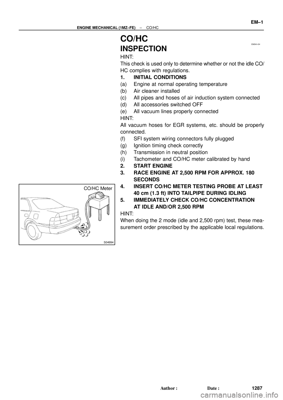
CO/HC Meter
± ENGINE MECHANICAL (1MZ±FE)CO/HC
EM±1
1287 Author�: Date�:
CO/HC
INSPECTION
HINT:
This check is used only to determine whether or not the idle CO/
HC complies with regulations.
1. INITIAL CONDITIONS
(a) Engine at normal operating temperature
(b) Air cleaner installed
(c) All pipes and hoses of air induction system connected
(d) All accessories switched OFF
(e) All vacuum lines properly connected
HINT:
All vacuum hoses for EGR systems, etc. should be properly
connected.
(f) SFI system wiring connectors fully plugged
(g) Ignition timing check correctly
(h) Transmission in neutral position
(i) Tachometer and CO/HC meter calibrated by hand
2. START ENGINE
3. RACE ENGINE AT 2,500 RPM FOR APPROX. 180
SECONDS
4. INSERT CO/HC METER TESTING PROBE AT LEAST
40 cm (1.3 ft) INTO TAILPIPE DURING IDLING
5. IMMEDIATELY CHECK CO/HC CONCENTRATION
AT IDLE AND/OR 2,500 RPM
HINT:
When doing the 2 mode (idle and 2,500 rpm) test, these mea-
surement order prescribed by the applicable local regulations.