Page 2427 of 4770

DI±7
242 Author�: Date�:
3. INSPECT DIAGNOSIS (Check Mode)
HINT:
TOYOTA hand±held tester only:
Compared to the normal mode, the check")
FI3605
ON
OFFFlashing
0.13 Second
± DIAGNOSTICSENGINE (5S±FE)
DI±7
242 Author�: Date�:
3. INSPECT DIAGNOSIS (Check Mode)
HINT:
TOYOTA hand±held tester only:
Compared to the normal mode, the check mode has an in-
creased sensitivity to detect malfunctions.
Furthermore, the same diagnostic items which are detected in
the normal mode can also be detected in the check mode.
(a) Check the DTC.
(1) Initial conditions
�Battery positive voltage 11 V or more
�Throttle valve fully closed
�Transmission in P or N position
�Air conditioning switched OFF
(2) Turn ignition switch OFF.
(3) Prepare the TOYOTA hand±held tester.
(4) Connect the TOYOTA hand±held tester to the
DLC3 under the instrument panel lower pad.
(5) Turn the ignition switch ON and switch the TOYOTA
hand±held tester ON.
(6) Switch the TOYOTA hand±held tester normal mode
to check mode. (Check that the MIL flashes.)
NOTICE:
If the TOYOTA hand±held tester switches the ECM from
normal mode to check mode or vice±versa, or if the igni-
tion switch is turned from ON to ACC or LOCK during check
mode, the DTCs and freezed frame data will be erased.
(7) Start the engine. (The MIL goes out after the engine
start.)
(8) Simulate the conditions of the malfunction de-
scribed by the customer.
NOTICE:
Leave the ignition switch ON until you have checked the
DTC, etc.
(9) After simulating the malfunction conditions, use the
TOYOTA hand±held tester diagnosis selector to
check the DTCs and freezed frame data, etc.
HINT:
Take care not to turn the ignition switch OFF. Turning the ignition
switch OFF switches the diagnosis system from check mode to
normal mode. So all DTCs, etc. are erased.
(10) After checking the DTC, inspect the applicable cir-
cuit.
Page 2430 of 4770
DI±10
± DIAGNOSTICSENGINE (5S±FE)
245 Author�: Date�:
5 Check idle speed.
PREPARATION:
(a) Warm up the engine to normal operating temperature.
(b) Switch off all the accessories.
(c) Switch off the air conditioning.
(d) Shift the transmission into the N position.
(e) Connect the OBD II scan tool or TOYOTA hand±held tester to DLC3 on the vehicle.
CHECK:
Use the CURRENT DATA to check the idle speed.
OK:
Idle speed: 650 ~ 750 rpm
NG Proceed to problem symptoms table on
page DI±28.
OK
Page 2431 of 4770
A07370S05309A07664
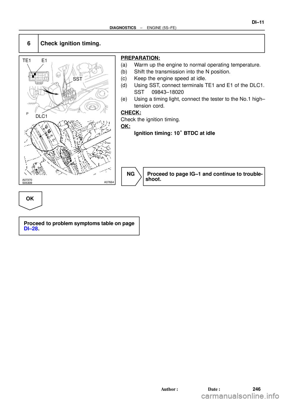
E1 TE1
SST
DLC1
± DIAGNOSTICSENGINE (5S±FE)
DI±11
246 Author�: Date�:
6 Check ignition timing.
PREPARATION:
(a) Warm up the engine to normal operating temperature.
(b) Shift the transmission into the N position.
(c) Keep the engine speed at idle.
(d) Using SST, connect terminals TE1 and E1 of the DLC1.
SST 09843±18020
(e) Using a timing light, connect the tester to the No.1 high±
tension cord.
CHECK:
Check the ignition timing.
OK:
Ignition timing: 10° BTDC at idle
NG Proceed to page IG±1 and continue to trouble-
shoot.
OK
Proceed to problem symptoms table on page
DI±28.
Page 2444 of 4770

259 Author�: Date�:
Symbols (Terminals No.)Wiring ColorConditionSTD Voltage (V)
*1GBR
IdlingBelow 3.01
HTAF (E9 ± 2) ± E04 (E9 ± 15)G e BR
IG switch ON9 ~ 14
LO")
DI±24
± DIAGNOSTICSENGINE (5S±FE)
259 Author�: Date�:
Symbols (Terminals No.)Wiring ColorConditionSTD Voltage (V)
*1GBR
IdlingBelow 3.01
HTAF (E9 ± 2) ± E04 (E9 ± 15)G e BR
IG switch ON9 ~ 14
LOCK IN (E9 ± 18)
± E1 (E9 ± 14)W ± L e BRA/C compressor is operatingPulse generation
(See page DI±190)
LOCK (E7 15) E1(E9 14)RWBRA/C indicator light lights upBelow 4.0LOCK (E7 ± 15) ± E1(E9 ± 14)R ± W e BRA/C indicator light does not lights upBelow 1.0
A/C SW (E7 ± 10)RBBRA/C switch ON9 ~ 14A/C SW (E7 10)
± E1 (E9 ± 14)R ± B e BRA/C switch OFFBelow 1.0
PRS (E7 ± 13) ± E1 (E9 ± 14)G e BRA/C pressure is normallyBelow 1.0
THR (E8 10) E2 (E8 9)LRBRIG switch ON, A/C evaporator temp. 0°C (32°F)2.2 ~ 2.6THR (E8 ± 10) ± E2 (E8 ± 9)L ± R e BRIG switch ON, A/C evaporator temp. 15°C (59°F)1.4 ~ 1.8
MGC (E7 21) E01(E9 14)LYBRA/C magnetic clutch ONBelow 1.0MGC (E7 ± 21) ± E01(E9 ± 14)L ± Y e BRA/C magnetic clutch OFF9 ~ 14
* STP (E7 4) E1 (E9 14)GWBRIG switch ON, Brake pedal depressed7.5 ~ 14* STP (E7 ± 4) ± E1 (E9 ± 14)G ± W e BRIG switch ON, Brake pedal releasedBelow 1.5
ELS (E7 2) E1 (E9 14)BRBRDefogger switch and taillight switch ON7.5 ~ 14ELS (E7 ± 2) ± E1 (E9 ± 14)B ± R e BRDefogger switch and taillight switch OFFBelow 1.5
PSSW (E8 ± 12) BLBRIG switch ON9 ~ 14PSSW (E8 12)
± E1 (E9 ± 14)B ± L e BRAt idling, Turn steering wheel to lock positionBelow 3.0
SIL (E7 ± 16) ± E1 (E9 ± 14)W e BRDuring transmissionPulse generation
*: Only for A/T models
*1: Only for California Specification vehicles
Page 2447 of 4770

DI±27
262 Author�: Date�:
Symbols (Terminals No.)Wiring ColorConditionSTD Voltage (V)
*1GBR
IdlingBelow 3.01
HTAF (E9 ± 2) ± E04 (E9 ± 15)G e BR
IG switch ON9 ~ 14
LO")
± DIAGNOSTICSENGINE (5S±FE)
DI±27
262 Author�: Date�:
Symbols (Terminals No.)Wiring ColorConditionSTD Voltage (V)
*1GBR
IdlingBelow 3.01
HTAF (E9 ± 2) ± E04 (E9 ± 15)G e BR
IG switch ON9 ~ 14
LOCK IN (E9 ± 19)
± E1 (E9 ± 24)W ± L e BRA/C compressor is operatingPulse generation
(See page DI±190)
LOCK (E7 ± 20)RWBRA/C indicator light lights upBelow 4.0LOCK (E7 20)
± E1 (E9 ± 24)R ± W e BRA/C indicator light does not lights upBelow 1.0
A/C SW (E7 ± 10)RBBRA/C switch ON9 ~ 14A/C SW (E7 10)
± E1 (E9 ± 24)R ± B e BRA/C switch OFFBelow 1.0
PRS (E7 ± 19) ± E1 (E9 ± 24)G e BRA/C pressure is normallyBelow 1.0
THR (E8 11) E2 (E8 9)LRBRIG switch ON, A/C evaporator temp. 0°C (32°F)2.2 ~ 2.6THR (E8 ± 11) ± E2 (E8 ± 9)L ± R e BRIG switch ON, A/C evaporator temp. 15°C (59°F)1.4 ~ 1.8
MGC (E7 ± 21)LYBRA/C magnetic clutch ONBelow 1.0MGC (E7 21)
± E01 (E9 ± 13)L ± Y e BRA/C magnetic clutch OFF9 ~ 14
* STP (E7 9) E1 (E9 24)GWBRIG switch ON, Brake pedal depressed7.5 ~ 14* STP (E7 ± 9) ± E1 (E9 ± 24)G ± W e BRIG switch ON, Brake pedal releasedBelow 1.5
ELS (E7 13) E1 (E9 24)BRBRDefogger switch and taillight switch ON7.5 ~ 14ELS (E7 ± 13) ± E1 (E9 ± 24)B ± R e BRDefogger switch and taillight switch OFFBelow 1.5
PSSW (E9 ± 4) BLBRIG switch ON9 ~ 14PSSW (E9 4)
± E1 (E9 ± 24)B ± L e BRAt idling, Turn steering wheel to lock positionBelow 3.0
SIL (E7 ± 6) ± E1 (E9 ± 24)W e BRDuring transmissionPulse generation
TACH (E7 ± 7) ± E1 (E9 ± 24)B ± O eBRIdlingPulse generation
KSW (E10 4) E1 (E9 24)LBBRAt the time of inserting keyBelow 1.5KSW (E10 ± 4) ± E1 (E9 ± 24)L ± B e BRIn the condition without key insertedPulse generation
RXCK (E10 ± 3)
± E1 (E9 ± 24)R ± L eBRAt the time of inserting keyPulse generation
CODE (E10 ± 8)
± E1 (E9 ± 24)G ± W eBRAt the time of inserting keyPulse generation
TXCT (E10 ± 1)
± E1 (E9 ± 24)L ± Y eBRAt the time of inserting keyPulse generation
IMLD (E10 ± 1) ± E1 (E9 ± 24)R ± Y eBRIn the condition without key insertedPulse generation
MREL (E10 ± 7)
± E1 (E9 ± 24)B ± W eBRIG switch ON9 ~ 14
IGSW (E7 ± 1) ± E1 (E9 ± 24)B ± ReBRIG switch ON9 ~ 14
*: Only for A/T models
*1: Only for California Specification vehicles
Page 2565 of 4770

A00414
No.1 Vehicle
Speed Sensor4±Pulse 4±Pulse
Combination Meter
ECM
Transaxle
No.1 Vehicle Speed Sensor
A03601
Combination Meter
14
V±WV±W
B J15
J/C
IG3
BV±W9
E7SPD5 V ECM
3
C9
*1: w/o Immobiliser
*2: w/ Immobiliser(*1) (*2)
E7 8
± DIAGNOSTICSENGINE (5S±FE)
DI±145
380 Author�: Date�:
DTC P0500 Vehicle Speed Sensor Malfunction
CIRCUIT DESCRIPTION
The No.1 vehicle speed sensor outputs a 4±pulse signal for every revolution of the rotor shaft, which is ro-
tated by the transmission output shaft via the driven gear. After this signal is converted into a more precise
rectangular waveform by the waveform shaping circuit inside the combination meter, it is then transmitted
to the ECM. The ECM determines the vehicle speed based on the frequency of these pluse signals.
DTC No.DTC Detecting ConditionTrouble Area
P0500
During vehicle is being driven, no vehicle speed sensor signal
to ECM
(2 trip detection logic)�Combination meter
�Open or short in No.1 vehicle speed sensor circuit
�No.1 vehicle speed sensor
�ECM
WIRING DIAGRAM
DI01B±10
Page 2569 of 4770

DI±149
384 Author�: Date�:
INSPECTION PROCEDURE
HINT:
Read freeze frame data using TOYOTA hand±held tester or OBD II scan tool. Because freeze frame records
the engine")
± DIAGNOSTICSENGINE (5S±FE)
DI±149
384 Author�: Date�:
INSPECTION PROCEDURE
HINT:
Read freeze frame data using TOYOTA hand±held tester or OBD II scan tool. Because freeze frame records
the engine conditions when the malfunction is detected, when troubleshooting it is useful for determining
whether the vehicle was running or stopped, the engine warmed up or not, the air±fuel ratio lean or rich, etc.
at the time of the malfunction.
1 Check idle speed.
PREPARATION:
(a) Warm up the engine to normal operating temperature.
(b) Switch off all the accessories.
(c) Switch off the air conditioning.
(d) Shift the transmission into N or neutral position.
(e) Connect the OBD II scan tool or TOYOTA hand±held tester to the DLC3 on the vehicle.
(f) Using SST, connect terminals TE1 and E1 of the DLC1.
CHECK:
Check the difference of engine speed between the ones less than 5 sec. and more than 5 sec. after connect-
ing terminals TE1 and E1 of the DLC1.
OK:
Difference of engine speed: More than 100 rpm
OK Go to step 6.
NG
Page 2619 of 4770

DI±199
434 Author�: Date�:
(b) Check the DLC3.
The vehicles ECM uses ISO 9141±2 for communication.
The terminal arrangement of DLC3 complies with S")
N09214
DLC3
S04159
± DIAGNOSTICSENGINE (1MZ±FE)
DI±199
434 Author�: Date�:
(b) Check the DLC3.
The vehicle's ECM uses ISO 9141±2 for communication.
The terminal arrangement of DLC3 complies with SAE
J1962 and matches the ISO 9141±2 format.
Terminal No.Connection / Voltage or ResistanceCondition
7Bus � Line / Pulse generationDuring transmission
4Chassis Ground e Body Ground /1 W or lessAlways
5Signal Ground e Body Ground /1 W or lessAlways
16Battery Positive e Body Ground /9 ~ 14 VAlways
HINT:
If your display shows ºUNABLE TO CONNECT TO VEHICLEº
when you have connected the cable of the OBD II scan tool or
TOYOTA hand±held tester to DLC3, turned the ignition switch
ON and operated the scan tool, there is a problem on the ve-
hicle side or tool side.
�If communication is normal when the tool is connected to
another vehicle, inspect DLC3 on the original vehicle.
�If communication is still not possible when the tool is con-
nected to another vehicle, the problem is probably in the
tool itself, so consult the Service Department listed in the
tool's instruction manual.
2. INSPECT DIAGNOSIS (Normal Mode)
(a) Check the MIL.
(1) The MIL comes on when the ignition switch is turned
ON and the engine is not running.
HINT:
If the MIL does not light up, troubleshoot the combination meter
(See page BE±46).
(2) When the engine started, the MIL should go off. If
the lamp remains on, the diagnosis system has de-
tected a malfunction or abnormality in the system.
(b) Check the DTC.
NOTICE:
TOYOTA hand±held tester only: When the diagnosis sys-
tem is switched from normal mode to check mode, it erases
all DTC and freezed frame data recorded in normal mode.
So before switching modes, always check the DTC and
freezed frame data, and note them down.
(1) Prepare the OBD II scan tool (complying with SAE
J1978) or TOYOTA hand±held tester.