Page 3584 of 4770
ENGINE UNIT
1364 Author�: Date�:
14. INSTALL PS PUMP
(a) Install the PS pump with the 2 bolts.
Torque: 43 N´m (440")
P18775
B00881
ConnectorBracket
A
B
A
A
C
S04497
EM±78
± ENGINE MECHANICAL (1MZ±FE)ENGINE UNIT
1364 Author�: Date�:
14. INSTALL PS PUMP
(a) Install the PS pump with the 2 bolts.
Torque: 43 N´m (440 kgf´cm, 31 ft´lbf)
(b) Install the drive belt.
(c) Connect the PS pressure tube with the 2 nuts.
15. INSTALL A/C COMPRESSOR
(a) Install the A/C compressor and drive belt adjusting bar
bracket with the 4 bolts and nut.
Torque:
Bolt A: 25 N´m (250 kgf´cm, 18 ft´lbf)
Bolt B: 18 N´m (185 kgf´cm, 13 ft´lbf)
Nut C: 25 N´m (250 kgf´cm, 18 ft´lbf)
(b) Install the drive belt.
(c) Connect the A/C compressor connector.
16. M/T only:
INSTALL CLUTCH RELEASE CYLINDER AND
ACCUMULATOR
17. M/T only:
INSTALL STARTER (See page ST±19)
18. INSTALL DRIVE SHAFTS (See page SA±32)
19. CONNECT ENGINE WIRE TO CABIN
(a) Push in the engine wire through the cowl panel. Install the
grommet.
(b) Connect the 3 engine ECM connectors.
(c) Connect the 3 cowl wire connectors to the connectors on
the bracket.
(d) Install the No.2 instrument lower panel.
20. CONNECT CONNECTORS, CABLE, CLAMPS AND
HOSES
(a) Connect the igniter connector on the LH fender apron.
(b) Connect the noise filter connector on the LH fender
apron.
(c) Connect the generator connector and wire.
(d) Connect the starter connector and wire.
(e) Connect the 2 ground strap connectors to the RH fender
apron.
Page 3585 of 4770
ENGINE UNIT
EM±79
1365 Author�: Date�:
(f) Connect the 2 ground strap connectors to the LH fender
apron.
(g) Connect the DLC1 to the RH fender apron.
(h) Connect")
S05048
± ENGINE MECHANICAL (1MZ±FE)ENGINE UNIT
EM±79
1365 Author�: Date�:
(f) Connect the 2 ground strap connectors to the LH fender
apron.
(g) Connect the DLC1 to the RH fender apron.
(h) Connect the ground cable to the battery body bracket.
(i) Connect the engine wire protector clamp to the battery
body bracket.
(j) Connect the engine wire clamp to the bracket on the RH
fender apron.
(k) Connect the engine wire clamp to the bracket on the fuel
filter.
(l) Connect the brake booster vacuum hose to the air intake
chamber.
(m) Connect the engine coolant reservoir hose to the water
outlet.
(n) Connect the heater hose to the intake manifold.
(o) Connect the heater hose to the water inlet housing.
(p) Connect the fuel inlet hose to the fuel filter.
CAUTION:
Perform connecting operations of the fuel tube connector
(quick type) after observing the precautions.
(See page SF±6)
(q) Connect the purge hose to the pipe on the emission con-
trol valve set.
(r) Connect the 2 vacuum hoses to the vacuum tank for the
ACIS.
21. INSTALL FRONT EXHAUST PIPE
(a) Temporarily install 3 new gaskets and the front exhaust
pipe with the 2 bolts and 6 nuts.
(b) Tighten the 4 nuts holding the exhaust manifolds to the
front exhaust pipe.
Torque: 62 N´m (630 kgf´cm, 46 ft´lbf)
(c) Tighten the 2 bolts and 2 nuts holding the front exhaust
pipe to the center exhaust pipe.
Torque: 56 N´m (570 kgf´cm, 41 ft´lbf)
(d) Install the bracket with the 2 bolts.
Torque: 33 N´m (330 kgf´cm, 24 ft´lbf)
(e) Install the support stay with the 2 bolts.
Torque: 33 N´m (330 kgf´cm, 24 ft´lbf)
22. INSTALL RADIATOR (See page CO±24)
23. INSTALL CRUISE CONTROL ACTUATOR
24. INSTALL AIR CLEANER CAP ASSEMBLY AND AIR
CLEANER CASE
25. CONNECT ACCELERATOR CABLE
26. INSTALL ENGINE FENDER APRON SEALS
27. INSTALL BATTERY TRAY AND BATTERY
Page 3586 of 4770
EM±80
± ENGINE MECHANICAL (1MZ±FE)ENGINE UNIT
1366 Author�: Date�:
28. INSTALL HOOD
29. FILL ENGINE WITH OIL
30. FILL WITH ENGINE COOLANT
31. START ENGINE AND CHECK FOR LEAKS
32. PERFORM ROAD TEST
Check for abnormal noise, shock, slippage, correct shift points
and smooth operation.
33. RECHECK ENGINE COOLANT AND OIL LEVELS
Page 3587 of 4770

No.2 Idler Pulley Bracket
Water Seal Plate
Engine Cool")
EM050±03
A06640
Knock Sensor Connector
Engine Wire Band
Engine WireKnock Sensor
No.2 ECT Switch Connector
Water Inlet Housing
(With Water Inlet)
No.2 Idler Pulley Bracket
Water Seal Plate
Engine Coolant
Drain Union
Oil Filter Union
Oil Filter � Gasket
EGR Cooler
� Gasket
Water Pump
� Crankshaft
Front Oil Seal
Crankshaft
Position Sensor
Connector� Oil Pressure Switch
Oil Pressure Switch
ConnectorA/C Compressor
Housing Bracket
No.1 Oil Pan
x 15 or 17 Oil Pump
� Gasket
� Gasket
Engine Wire
Generator
Drain Plugx 10No.2 Oil Pan Oil Strainer
� Non±reusable part
N´m (kgf´cm, ft´lbf) : Specified torque
Precoated part �
x 8
�
� O±Ring
x 9
9 (90, 78 in.´lbf)
8 (80, 69 in.´lbf)
10mm Head 7.8 (80, 69 in.´lbf)
12mm Head 19.5 (200,14)
39 (400, 29)
28 (290, 21)
14.5 (145, 10)
25 (250, 18)
10mm Head 8 (80, 69 in.´lbf)
12mm Head 19.5 (200,14)
8 (80, 69 in.´lbf)
8 (80, 69 in.´lbf)45 (460, 33)
8 (80, 69 in.´lbf)
or 0 or 0
± ENGINE MECHANICAL (1MZ±FE)CYLINDER BLOCK
EM±81
1367 Author�: Date�:
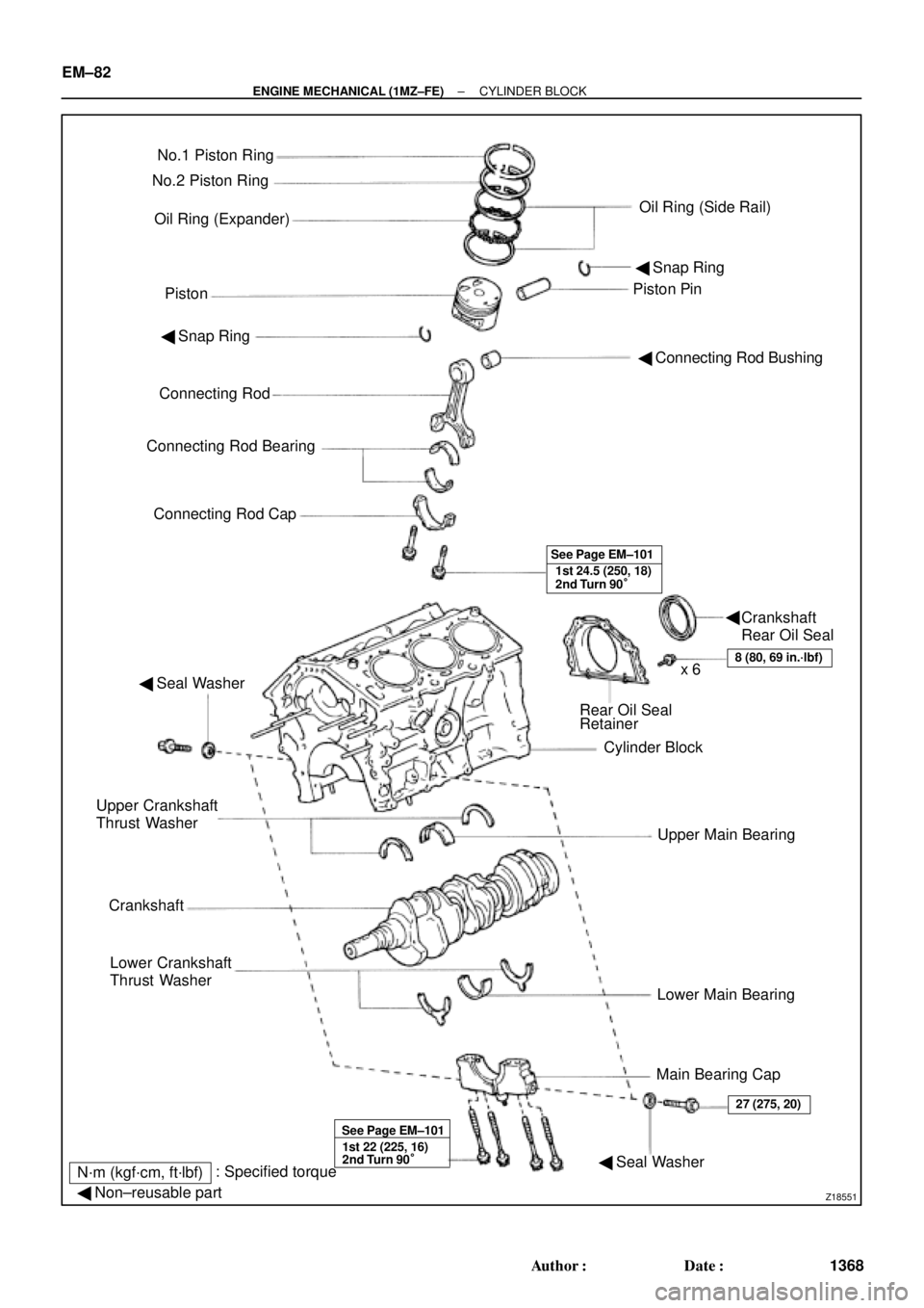
CYLINDER BLOCK
COMPONENTS
Page 3588 of 4770
Z18551
No.1 Piston Ring
Oil Ring (Expander)
PistonPiston Pin No.2 Piston Ring
Oil Ring (Side Rail)
� Snap Ring
� Connecting Rod Bushing � Snap Ring
Connecting Rod
Connecting Rod Bearing
Connecting Rod Cap
1st 24.5 (250, 18)
2nd Turn 90° See Page EM±101
� Seal Washer
Rear Oil Seal
Retainer
Cylinder Block
Upper Main Bearing
Lower Main Bearing
Main Bearing Cap Upper Crankshaft
Thrust Washer
Crankshaft
Lower Crankshaft
Thrust Washer
8 (80, 69 in.´lbf)x 6
1st 22 (225, 16)
2nd Turn 90° See Page EM±101
� Seal Washer
27 (275, 20)
N´m (kgf´cm, ft´lbf): Specified torque
� Non±reusable part
Crankshaft
Rear Oil Seal � EM±82
± ENGINE MECHANICAL (1MZ±FE)CYLINDER BLOCK
1368 Author�: Date�:
Page 3589 of 4770
EM051±04
S04921
P12946
P18761
P12389
SST
± ENGINE MECHANICAL (1MZ±FE)CYLINDER BLOCK
EM±83
1369 Author�: Date�:
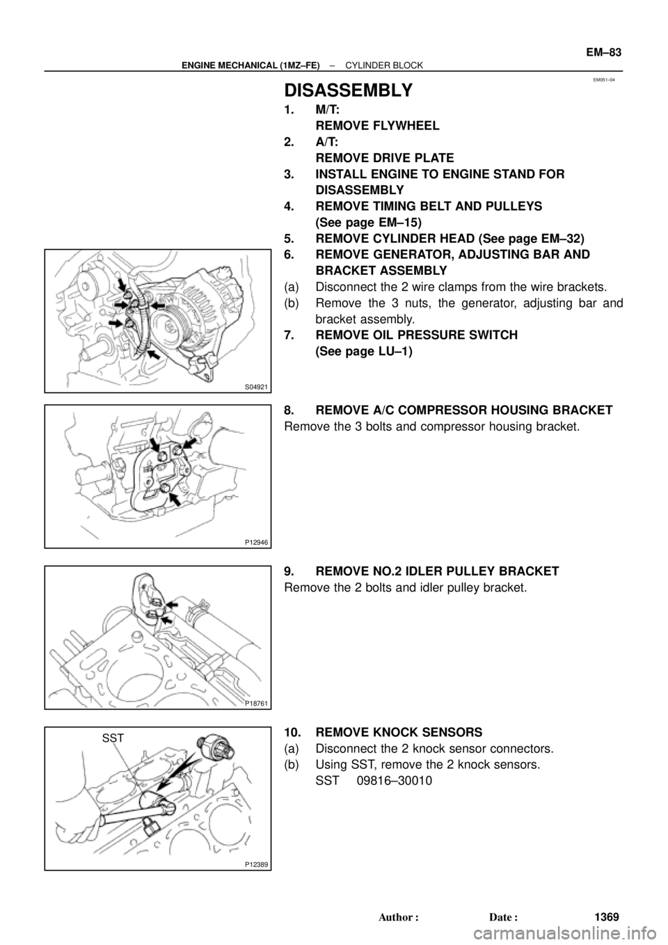
DISASSEMBLY
1. M/T:
REMOVE FLYWHEEL
2. A/T:
REMOVE DRIVE PLATE
3. INSTALL ENGINE TO ENGINE STAND FOR
DISASSEMBLY
4. REMOVE TIMING BELT AND PULLEYS
(See page EM±15)
5. REMOVE CYLINDER HEAD (See page EM±32)
6. REMOVE GENERATOR, ADJUSTING BAR AND
BRACKET ASSEMBLY
(a) Disconnect the 2 wire clamps from the wire brackets.
(b) Remove the 3 nuts, the generator, adjusting bar and
bracket assembly.
7. REMOVE OIL PRESSURE SWITCH
(See page LU±1)
8. REMOVE A/C COMPRESSOR HOUSING BRACKET
Remove the 3 bolts and compressor housing bracket.
9. REMOVE NO.2 IDLER PULLEY BRACKET
Remove the 2 bolts and idler pulley bracket.
10. REMOVE KNOCK SENSORS
(a) Disconnect the 2 knock sensor connectors.
(b) Using SST, remove the 2 knock sensors.
SST 09816±30010
Page 3590 of 4770
CYLINDER BLOCK
1370 Author�: Date�:
11. REMOVE WATER I")
P18762
P18763
WaterSeal
Plate
Oil Filter
Union
12 mm
Hexagon
Wrench
Coolant
Drain
Union
P12410
P12508
P12695
EM±84
± ENGINE MECHANICAL (1MZ±FE)CYLINDER BLOCK
1370 Author�: Date�:
11. REMOVE WATER INLET HOUSING
(a) Remove the engine wire band.
(b) Disconnect the engine wire clamp from the bracket.
(c) Remove the 8 bolts, 2 nuts and water inlet housing.
12. REMOVE WATER PUMP (See page CO±6)
13. REMOVE NO.2 OIL PAN (See page LU±9)
14. REMOVE OIL STRAINER (See page LU±9)
15. REMOVE NO.1 OIL PAN (See page LU±9)
16. REMOVE OIL PUMP (See page LU±9)
17. REMOVE OIL FILTER (See page LU±9)
18. REMOVE OIL FILTER UNION
Using a 12 mm hexagon wrench, remove the oil filter union.
19. REMOVE WATER SEAL PLATE
Remove the 2 nuts and seal plate.
20. REMOVE ENGINE COOLANT DRAIN UNION
21. REMOVE EGR COOLER
Remove the 3 bolts, 2 nuts, EGR cooler and gasket.
22. REMOVE REAR OIL SEAL RETAINER
(a) Remove the 6 bolts.
(b) Using a screwdriver, remove the oil seal retainer by prying
the portions between the oil seal retainer and main bear-
ing cap.
23. CHECK CONNECTING ROD THRUST CLEARANCE
Using a dial indicator, measure the thrust clearance while mov-
ing the connecting rod back and forth.
Standard thrust clearance:
0.15 ± 0.30 mm (0.0059 ± 0.0118 in.)
Maximum thrust clearance: 0.35 mm (0.0138 in.)
If the thrust clearance is greater than maximum, replace the
connecting rod assembly(s). If necessary, replace the crank-
shaft.
Page 3591 of 4770
P13329
P12707
P12696
P12728
Plastigage
± ENGINE MECHANICAL (1MZ±FE)CYLINDER BLOCK
EM±85
1371 Author�: Date�:
Connecting rod thickness:
20.80 ± 20.85 mm (0.8189 ± 0.8209 in.)
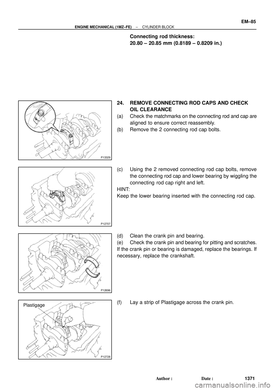
24. REMOVE CONNECTING ROD CAPS AND CHECK
OIL CLEARANCE
(a) Check the matchmarks on the connecting rod and cap are
aligned to ensure correct reassembly.
(b) Remove the 2 connecting rod cap bolts.
(c) Using the 2 removed connecting rod cap bolts, remove
the connecting rod cap and lower bearing by wiggling the
connecting rod cap right and left.
HINT:
Keep the lower bearing inserted with the connecting rod cap.
(d) Clean the crank pin and bearing.
(e) Check the crank pin and bearing for pitting and scratches.
If the crank pin or bearing is damaged, replace the bearings. If
necessary, replace the crankshaft.
(f) Lay a strip of Plastigage across the crank pin.