Page 3616 of 4770
P00601
Adhesive
A05416
1
2 34 5
67
8
EM±110
± ENGINE MECHANICAL (1MZ±FE)CYLINDER BLOCK
1396 Author�: Date�:
30. INSTALL OIL PRESSURE SWITCH
(See page LU±1)
31. INSTALL GENERATOR, BRACKET AND
ADJUSTING BAR ASSEMBLY
Torque: 43 N´m (440 kgf´cm, 32 ft´lbf)
32. INSTALL CYLINDER HEAD (See page EM±57)
33. INSTALL TIMING PULLEYS AND BELT
(See page EM±21)
34. REMOVE ENGINE STAND
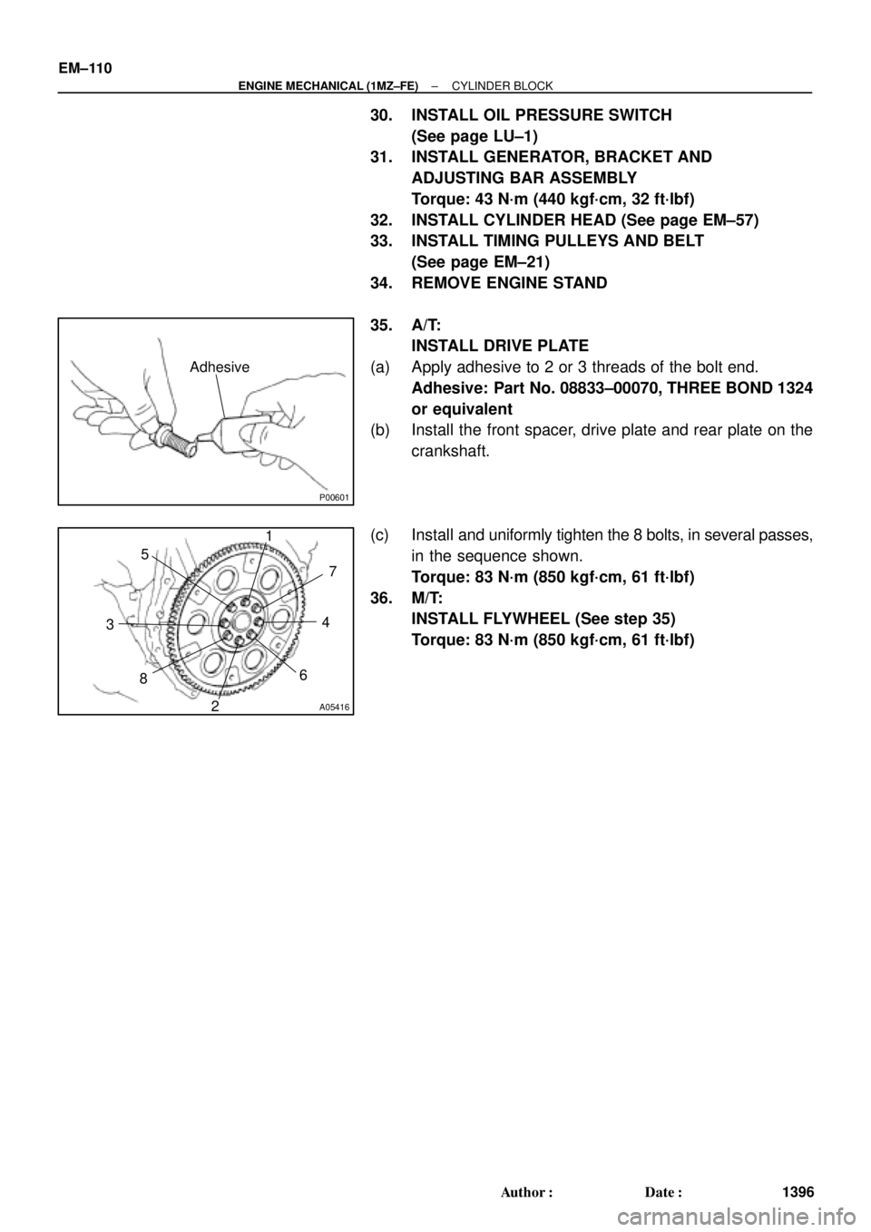
35. A/T:
INSTALL DRIVE PLATE
(a) Apply adhesive to 2 or 3 threads of the bolt end.
Adhesive: Part No. 08833±00070, THREE BOND 1324
or equivalent
(b) Install the front spacer, drive plate and rear plate on the
crankshaft.
(c) Install and uniformly tighten the 8 bolts, in several passes,
in the sequence shown.
Torque: 83 N´m (850 kgf´cm, 61 ft´lbf)
36. M/T:
INSTALL FLYWHEEL (See step 35)
Torque: 83 N´m (850 kgf´cm, 61 ft´lbf)
Page 3617 of 4770
EM0YU±01
A06653
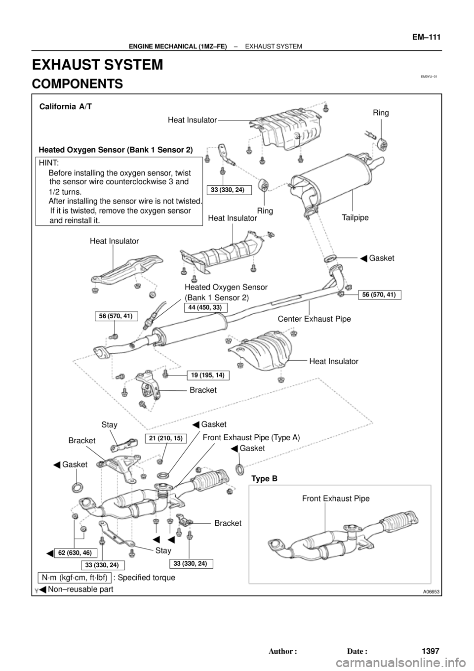
� Gasket
� Non±reusable part
N´m (kgf´cm, ft´lbf) : Specified torque� Gasket
�
�
�BracketFront Exhaust Pipe Bracket
StayHeat Insulator Center Exhaust Pipe� Gasket Heat InsulatorHeat Insulator
Heated Oxygen Sensor
(Bank 1 Sensor 2)TailpipeRing
Ring
33 (330, 24)
Heat Insulator
Heated Oxygen Sensor (Bank 1 Sensor 2)
� Before installing the oxygen sensor, twist
the sensor wire counterclockwise 3 and
1/2 turns.
If it is twisted, remove the oxygen sensor
and reinstall it. � After installing the sensor wire is not twisted. California A/T
Bracket
HINT:
56 (570, 41)
19 (195, 14)
21 (210, 15)
62 (630, 46)
33 (330, 24)33 (330, 24)
56 (570, 41)
Stay
Front Exhaust Pipe (Type A)
Type B
44 (450, 33)
� Gasket
± ENGINE MECHANICAL (1MZ±FE)EXHAUST SYSTEM
EM±111
1397 Author�: Date�:
EXHAUST SYSTEM
COMPONENTS
Page 3618 of 4770
A06652
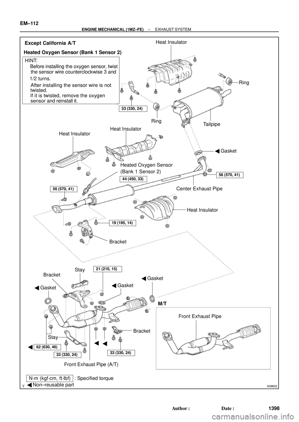
� Gasket
� Non±reusable part
N´m (kgf´cm, ft´lbf) : Specified torque� Gasket
�
�� Gasket
�Bracket
Stay
Front Exhaust Pipe (A/T) BracketBracket
Stay
21 (210, 15)
Heat Insulator Center Exhaust Pipe� Gasket Heat InsulatorHeat Insulator
Heated Oxygen Sensor
(Bank 1 Sensor 2)TailpipeRing
Ring
33 (330, 24)
Heat Insulator
Heated Oxygen Sensor (Bank 1 Sensor 2)
� Before installing the oxygen sensor, twist
the sensor wire counterclockwise 3 and
1/2 turns.
If it is twisted, remove the oxygen
sensor and reinstall it. � After installing the sensor wire is notExcept California A/T
HINT:
56 (570, 41)
19 (195, 14)
62 (630, 46)
33 (330, 24)33 (330, 24)
56 (570, 41)
twisted.
Front Exhaust Pipe
M/T
44 (450, 33)
EM±112
± ENGINE MECHANICAL (1MZ±FE)EXHAUST SYSTEM
1398 Author�: Date�:
Page 3643 of 4770
Tester connection
ConditionSpecified condition
1 ± Grou")
Z08523
1
2
341 2
43
I21683
12
34
1
2 4
3
55
± BODY ELECTRICALHEADLIGHT AND TAILLIGHT SYSTEM
BE±25
2235 Author�: Date�:
2001 CAMRY (RM819U)Tester connection
ConditionSpecified condition
1 ± GroundConstantBattery positive voltage
2 ± GroundConstantBattery positive voltage
3 ± GroundConstantBattery positive voltage
4 ± GroundLight control switch position OFF or HEADNo voltage
4 ± GroundLight control switch position TAILContinuity
5 ± GroundConstantBattery positive voltage
7 ± GroundLight control switch position OFF or TAILNo continuity
7 ± GroundLight control switch position HEADContinuity
8 ± GroundHeadlight dimmer switch position
Low beamNo continuity
8 ± GroundHeadlight dimmer switch position
High beam of FlashContinuity
9 ± GroundEngine StopNo voltage
9 ± GroundEngine RunningBattery positive voltage
10 ± GroundIgnition switch position LOCK or ACCNo voltage
10 ± GroundIgnition switch position ON or STARTBattery positive voltage
14 ± GroundConstantContinuity
17 ± GroundBrake fluid level warning position OFFNo continuity
17 ± GroundBrake fluid level warning position ONContinuity
18 ± GroundParking brake switch position OFF
(Parking brake lever released)No continuity
18 ± GroundParking brake switch position ON
(Parking brake lever pulled up)Continuity
If circuit is as specified, try replacing the relay with a new one.
If circuit is not as specified, inspect the circuits connected to oth-
er parts.
6. w/ Daytime running light system:
INSPECT DAYTIME RUNNING LIGHT NO.2 RELAY
CONTINUITY
ConditionTester connectionSpecified condition
Constant1 ± 4, 2 ± 4Continuity
Apply B+ between
terminals 2 and 4.3 ± 4Continuity
If continuity is not as specified, replace the relay.
7. w/ Daytime running light system:
INSPECT DAYTIME RUNNING LIGHT NO.3 RELAY-
CONTINUITY
ConditionTester connectionSpecified condition
Constant1 ± 2, 3 ± 4Continuity
Apply B+ between
terminals 1 and 2.3 ± 5Continuity
If continuity is not as specified, replace the relay.
Page 3646 of 4770

ADJUSTMENT
ADJUST HEADLIGHT AIM ONLY
(a) Place")
BE20X±01
I21909
For Adjustment
in Vertical Direction
BE±28
± BODY ELECTRICALHEADLIGHT AND TAILLIGHT SYSTEM
2238 Author�: Date�:
2001 CAMRY (RM819U)
ADJUSTMENT
ADJUST HEADLIGHT AIM ONLY
(a) Place the vehicle in the following conditions.
�The area around the headlight is not deformed.
�The vehicle is parked on a level surface.
�Tire inflation pressure is the specified value.
�A driver is in the driver's seat and the vehicle is in a state ready for driving (with a tank full).
�The vehicle has been bounced several times.
(b) Check the headlight aiming.
(1) Prepare a thick white paper.
(2) Stand the paper perpendicular to the ground at the position 9.84 ft away from the headlights.
(3) Ensure that the center line of the vehicle and the paper face forms a 90±degree angle as shown
in the illustration.
(4) Draw a horizontal line (H line) on the paper, showing where the headlights should strike.
(5) Draw a vertical line (V line) to where the center line of the vehicle is to be.
(6) Draw 2 vertical lines to where the the headlights should strike (V RH and V LH lines).
(7) Draw a horizontal line (by connecting the both low beam center marks) to where the headlights
should strike (H RH and H LH lines).
HINT:
The H RH and H LH line is 0.4° below the horizontal line (H line) of the light axis.
(8) Start the engine.
Page 3648 of 4770

IG0DB±01
SPARK TEST
CHECK CONNECTION OF IGNITION COIL WITH
CHECK RESISTANCE OF HIGH±TENSION CORDS
CHECK POWER SUPPLY TO IGNITION COILS WITH
1. Turn ignition switch to ON.
2. Check that there is battery positive voltage at ignition
CHECK RESISTANCE OF IGNITION COILS
Resistance:
SecondaryCold Hot
9.7 ± 16.7 kW12.4 ± 19.6 kW
CHECK RESISTANCE OF SENSORS
Resistance: Cold Hot
Camshaft position sensor
Crankshaft position sensor835 ± 1,400 W
985 ± 1,600 W1,060 ± 1,645 W
1,265 ± 1,890 W
CHECK IGT SIGNAL FROM ECM
TRY ANOTHER IGNITERIGNITER CONNECTORS
(See step 2)
Maximum resistance: 25 kW per cord
IGNITERS
coil positive (+) terminal.
(See step 4)
(See steps 5 and 6)
(See page DI±22) NO
OK
OK
OK
OK
OK
BAD
BAD
BAD
BAD
BAD
BAD
Connect securely.
Replace cord(s).
Check wiring between ignition switch to ignition
Replace ignition coil(s) with igniter(s).
Replace sensor(s).
Check wiring between ECM and igniters, and coils with igniters.
then try another ECM.
± IGNITION (5S±FE)IGNITION SYSTEM
IG±1
1683 Author�: Date�:
IGNITION SYSTEM
ON±VEHICLE INSPECTION
NOTICE:
ºColdº and ºHotº in these sentences express the temperature of the coils themselves. ºColdº is from
±10°C (14°F) to 50°C (122°F) and ºHotº is from 50°C (122°F) to 100°C (212°F).
1. INSPECT SPARK TEST
Check that the spark occurs.
(1) Disconnect the high±tension cord from the spark plug.
(2) Remove the spark plug.
(3) Install the spark plug to the high±tension cord.
(4) Ground the spark plug.
(5) See if spark occurs while engine is being cranked.
NOTICE:
To prevent gasoline from being injected from injectors during this test, crank the engine for no more
than 5 ± 10 seconds at time.
If the spark does not occur, do the test as follows:
Page 3649 of 4770
IGNITION SYSTEM
1684 Author�: Date�:
2. INSPECT HIGH±TENSION CORDS
(a) Remove the high±tension cords.
Disco")
S05295
CORRECT
WRONG
S05542
Ohmmeter
IG0147
Megger
Ground
S03776
IG±2
± IGNITION (5S±FE)IGNITION SYSTEM
1684 Author�: Date�:
2. INSPECT HIGH±TENSION CORDS
(a) Remove the high±tension cords.
Disconnect the high±tension cords at the rubber boot. Do
not pull on the high±tension cords.
NOTICE:
Pulling on or bending the cords may damage the conductor
inside.
(b) Using an ohmmeter, measure the high±tension cord re-
sistance.
Maximum resistance: 25 kW per cord
If the resistance is greater than maximum, check the terminals.
If necessary, replace the high±tension cord.
(c) Reinstall the high±tension cords.
3. INSPECT SPARK PLUGS
NOTICE:
�Never use a wire brush for cleaning.
�Never attempt to adjust the electrode gap on a used
spark plug.
�Spark plugs should be replaced every 100,000 km
(60,000 miles).
(a) Disconnect the high±tension cords from the spark plugs.
(b) Inspect the electrode.
Using a megger (insulation resistance meter), measure
the insulation resistance.
Standard correct insulation resistance:
10 MW or more
If the resistance is less than specified, proceed to step (d).
HINT:
If a megger is not available, the following simple method of in-
spection provides fairly accurate results.
Simple Method:
�Quickly race the engine to 4,000 rpm 5 times.
�Remove the spark plug. (See step (c))
�Visually check the spark plug.
If the electrode is dry ... OK
If the electrode is wet ... Proceed to step (d)
�Reinstall the spark plug. (See step (g))
Page 3657 of 4770
IG047±03
S05284
Engine Moving Control Rod
No.2 RH Engine Mounting Bracket
Generator Drive Belt
RH Front Fender Apron SealPS Pump Drive BeltGround Strap Connector
N´m (kgf´cm, ft´lbf) : Specified torque
64 (650, 47)
64 (650, 47)
52 (530, 38)
IG±10
± IGNITION (5S±FE)CRANKSHAFT POSITION SENSOR
1692 Author�: Date�:
CRANKSHAFT POSITION SENSOR
COMPONENTS
 : Specified t")