Page 3710 of 4770

± INTRODUCTIONTERMS
IN±39
39 Author�: Date�:
OHVOverhead Valve
OPTOption
O/SOversize
P & BVProportioning And Bypass Valve
PCSPower Control System
PCVPositive Crankcase Ventilation
PKBParking Brake
PPSProgressive Power Steering
PSPower Steering
PTOPower Take±Off
R & PRack And Pinion
R/BRelay Block
RBSRecirculating Ball Type Steering
R/FReinforcement
RFSRigid Front Suspension
RRSRigid Rear Suspension
RHRight±Hand
RHDRight±Hand Drive
RLYRelay
ROMRead Only Memory
RrRear
RRRear±Engine Rear±Wheel Drive
RWDRear±Wheel Drive
SDNSedan
SENSensor
SICSStarting Injection Control System
SOCState Of Charge
SOHCSingle Overhead Camshaft
SPECSpecification
SPISingle Point Injection
SRSSupplemental Restraint System
SSMSpecial Service Materials
SSTSpecial Service Tools
STDStandard
STJCold±Start Fuel Injection
SWSwitch
SYSSystem
T/ATransaxle
TACHTachometer
TBIThrottle Body Electronic Fuel Injection
TCTurbocharger
TCCSTOYOTA Computer±Controlled System
TCVTiming Control Valve
TDCTop Dead Center
TEMP.Temperature
TEMSTOYOTA Electronic Modulated Suspension
Page 3712 of 4770

IN0CI±01
± INTRODUCTIONTERMS
IN±41
41 Author�: Date�:
GLOSSARY OF SAE AND TOYOTA TERMS
This glossary lists all SAE±J1930 terms and abbreviations used in this manual in compliance with SAE rec-
ommendations, as well as their TOYOTA equivalents.
SAE
ABBREVIATIONSSAE TERMSTOYOTA TERMS
( )±±ABBREVIATIONS
A/CAir ConditioningAir Conditioner
ACLAir CleanerAir Cleaner, A/CL
AIRSecondary Air InjectionAir Injection (AI)
APAccelerator Pedal±
B+Battery Positive Voltage+B, Battery Voltage
BAROBarometric PressureHAC
CACCharge Air CoolerIntercooler
CARBCarburetorCarburetor
CFIContinuous Fuel Injection±
CKPCrankshaft PositionCrank Angle
CLClosed LoopClosed Loop
CMPCamshaft PositionCam Angle
CPPClutch Pedal Position±
CTOXContinuous Trap Oxidizer±
CTPClosed Throttle PositionLL ON, Idle ON
DFIDirect Fuel Injection (Diesel)Direct Injection (DI)
DIDistributor Ignition±
DLC1
DLC2
DLC3Data Link Connector 1
Data Link Connector 2
Data Link Connector 31: Check Connector
2: Total Diagnosis Comunication Link (TDCL)
3: OBD II Diagnostic Connector
DTCDiagnostic Trouble CodeDiagnostic Code
DTMDiagnostic Test Mode±
ECLEngine Control Level±
ECMEngine Control ModuleEngine ECU (Electronic Control Unit)
ECTEngine Coolant TemperatureCoolant Temperature, Water Temperature (THW)
EEPROMElectrically Erasable Programmable Read Only Memory
Electrically Erasable Programmable Read Only Memory
(EEPROM),
Erasable Programmable Read Only Memory (EPROM)
EFEEarly Fuel EvaporationCold Mixture Heater (CMH), Heat Control Valve (HCV)
EGRExhaust Gas RecirculationExhaust Gas Recirculation (EGR)
EIElectronic IgnitionTOYOTA Distributorless Ignition (TDI)
EMEngine ModificationEngine Modification (EM)
EPROMErasable Programmable Read Only MemoryProgrammable Read Only Memory (PROM)
EVAPEvaporative EmissionEvaporative Emission Control (EVAP)
FCFan Control±
FEEPROMFlash Electrically Erasable Programmable
Read Only Memory±
FEPROMFlash Erasable Programmable Read Only Memory±
FFFlexible Fuel±
FPFuel PumpFuel Pump
GENGeneratorAlternator
GNDGroundGround (GND)
Page 3713 of 4770

IACIdle Air ControlIdle Speed Control (ISC)
IATIntake Air TemperatureIntake or Inlet Air Temperature")
IN±42
± INTRODUCTIONTERMS
42 Author�: Date�:
HO2SHeated Oxygen SensorHeated Oxygen Sensor (HO2S)
IACIdle Air ControlIdle Speed Control (ISC)
IATIntake Air TemperatureIntake or Inlet Air Temperature
ICMIgnition Control Module±
IFIIndirect Fuel InjectionIndirect Injection (IDL)
IFSInertia Fuel±Shutoff±
ISCIdle Speed Control±
KSKnock SensorKnock Sensor
MAFMass Air FlowAir Flow Meter
MAPManifold Absolute PressureManifold Pressure
Intake Vacuum
MCMixture Control
Electric Bleed Air Control Valve (EBCV)
Mixture Control Valve (MCV)
Electric Air Control Valve (EACV)
MDPManifold Differential Pressure±
MFIMultiport Fuel InjectionElectronic Fuel Injection (EFI)
MILMalfunction Indicator LampCheck Engine Lamp
MSTManifold Surface Temperature±
MVZManifold Vacuum Zone±
NVRAMNon±Volatile Random Access Memory±
O2SOxygen SensorOxygen Sensor, O2 Sensor (O2S)
OBDOn±Board DiagnosticOn±Board Diagnostic System (OBD)
OCOxidation Catalytic ConverterOxidation Catalyst Convert (OC), CCo
OPOpen LoopOpen Loop
PAIRPulsed Secondary Air InjectionAir Suction (AS)
PCMPowertrain Control Module±
PNPPark/Neutral Position±
PROMProgrammable Read Only Memory±
PSPPower Steering Pressure±
PTOXPeriodic Trap OxidizerDiesel Particulate Filter (DPF)
Diesel Particulate Trap (DPT)
RAMRandom Access MemoryRandom Access Memory (RAM)
RMRelay Module±
ROMRead Only MemoryRead Only Memory (ROM)
RPMEngine SpeedEngine Speed
SCSuperchargerSupercharger
SCBSupercharger BypassE±ABV
SFISequential Multiport Fuel InjectionElectronic Fuel Injection (EFI), Sequential Injection
SPLSmoke Puff Limiter±
SRIService Reminder Indicator±
SRTSystem Readiness Test±
STScan Tool±
TBThrottle BodyThrottle Body
TBIThrottle Body Fuel InjectionSingle Point Injection
Central Fuel Injection (Ci)
TCTurbochargerTurbocharger
TCCTorque Converter ClutchTorque Converter
Page 3715 of 4770
 :
TEMPERATURE RANGE ANTICIPATED BEFORE NEXT OIL CHANGE 10W ± 30
5W ± 30 PREFERRED
±20
°C °F020406080
±29 ±18 ±7 4 16 27100
38
LU03H±03
S05317
Curved
Tip
Ins")
B00319
Recommended Viscosity (SAE) :
TEMPERATURE RANGE ANTICIPATED BEFORE NEXT OIL CHANGE 10W ± 30
5W ± 30 PREFERRED
±20
°C °F020406080
±29 ±18 ±7 4 16 27100
38
LU03H±03
S05317
Curved
Tip
Insert
S05298
Oil Pressure Gauge
P13638
Adhesive
± LUBRICATION (5S±FE)OIL AND FILTER
LU±1
1647 Author�: Date�:
OIL AND FILTER
INSPECTION
1. CHECK ENGINE OIL QUALITY
Check the oil for deterioration, entry of water, discoloring or thin-
ning.
If the quality is visibly poor, replace the oil.
Oil grade:
API grade SJ, Energy±Conserving or ILSAC multi-
grade engine oil. SAE 5W±30 is the best choice for
your vehicle, for good fuel economy, and good start-
ing in cold weather.
2. CHECK ENGINE OIL LEVEL
After warming up the engine and then 5 minutes after the en-
gine stop, oil level should be between ºLº and ºFº of the dipstick.
If low, check for leakage and add oil up to ºFº mark.
NOTICE:
�Do not fill with engine oil above the ºFº mark.
�When inserting the oil dipstick, insert the curved tip
of the dipstick facing the same direction as the curve
of the guide.
�If the dipstick gets caught while inserting it, do not
force it in. Reconfirm the direction of the dipstick.
3. REMOVE OIL PRESSURE SWITCH AND INSTALL OIL
PRESSURE GAUGE
4. WARM UP ENGINE
Allow the engine to warm up to normal operating temperature.
5. CHECK OIL PRESSURE
Oil pressure:
At idle29 kPa (0.3 kgf/cm2, 4.3 psi) or more
At 3,000 rpm245 ± 490 kPa (2.5 ± 5.0 kgf/cm2, 36 ± 71 psi)
6. REMOVE OIL PRESSURE GAUGE AND REINSTALL
OIL PRESSURE SWITCH
(a) Remove the oil pressure gauge.
(b) Apply adhesive to 2 or 3 threads of the oil pressure switch.
Adhesive:
Part No. 08833±00080, THREE BOND 1344, LOCTITE
242 or equivalent
(c) Reinstall the oil pressure switch.
7. START ENGINE AND CHECK FOR OIL LEAKS
Page 3716 of 4770
OIL AND FILTER
1648 Author�: Date�:
REPLACEMENT
CAUTION:
�Prolonged and repeated contact with mineral oil will
result in the removal of natura")
LU03I±03
S05318
SST
S05319
LU±2
± LUBRICATION (5S±FE)OIL AND FILTER
1648 Author�: Date�:
REPLACEMENT
CAUTION:
�Prolonged and repeated contact with mineral oil will
result in the removal of natural fats from the skin,
leading to dryness, irritation and dermatitis. In addi-
tion, used engine oil contains potentially harmful
contaminants which may cause skin cancer.
�Care should be taken, therefore, when changing en-
gine oil to minimize the frequency and length of time
your skin is exposed to used engine oil. Protective
clothing and gloves that cannot be penetrated by oil
should be worn. The skin should be thoroughly
washed with soap and water, or use water±less hand
cleaner, to remove any used engine oil. Do not use
gasoline, thinners, or solvents.
�In order to preserve the environment, used oil and
used oil filters must be disposed of only at desig-
nated disposal sites.
1. DRAIN ENGINE OIL
(a) Remove the oil filler cap.
(b) Remove the oil drain plug, and drain the oil into a contain-
er.
2. REPLACE OIL FILTER
(a) Using SST, remove the oil filter.
SST 09228±06501
(b) Clean the oil filter contact surface on the oil filter mount-
ing.
(c) Lubricate the filter rubber gasket with clean engine oil.
(d) Tighten the oil filter by hand until the rubber gasket con-
tacts the seat of the filter mounting.
Page 3717 of 4770
S05320
SST
3/4
Turn
± LUBRICATION (5S±FE)OIL AND FILTER
LU±3
1649 Author�: Date�:
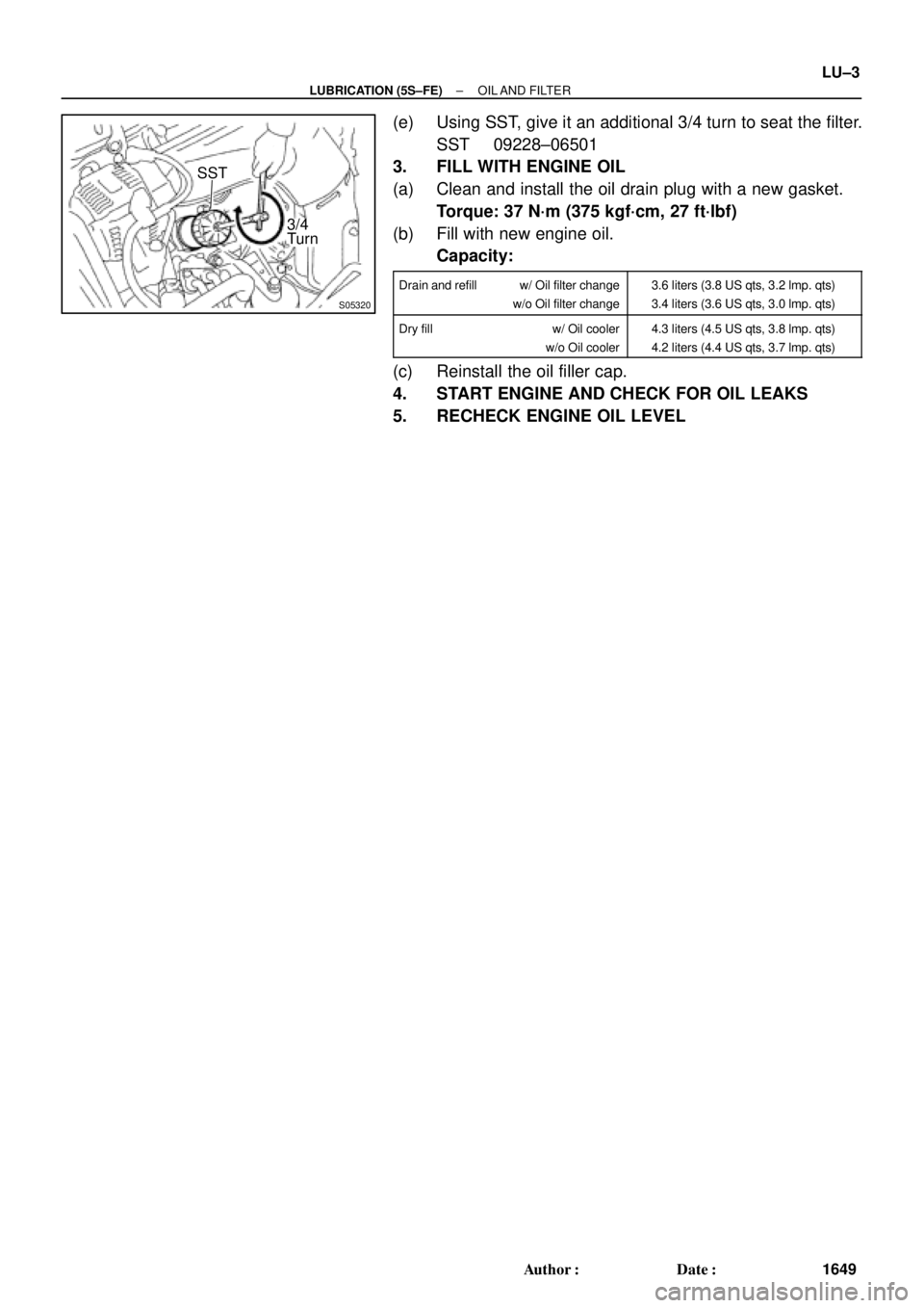
(e) Using SST, give it an additional 3/4 turn to seat the filter.
SST 09228±06501
3. FILL WITH ENGINE OIL
(a) Clean and install the oil drain plug with a new gasket.
Torque: 37 N´m (375 kgf´cm, 27 ft´lbf)
(b) Fill with new engine oil.
Capacity:
Drain and refill w/ Oil filter change
w/o Oil filter change3.6 liters (3.8 US qts, 3.2 lmp. qts)
3.4 liters (3.6 US qts, 3.0 lmp. qts)
Dry fill w/ Oil cooler
w/o Oil cooler4.3 liters (4.5 US qts, 3.8 lmp. qts)
4.2 liters (4.4 US qts, 3.7 lmp. qts)
(c) Reinstall the oil filler cap.
4. START ENGINE AND CHECK FOR OIL LEAKS
5. RECHECK ENGINE OIL LEVEL
Page 3718 of 4770
LU03J±03
S05595
Engine Moving Control Rod
No.2 RH Engine Mounting Bracket
Generator Drive Belt
RH Front Fender Apron Seal
PS Pump Drive Belt
Exhaust Pipe Bracket
Oil Pan InsulatorGround Strap Connector
No.2 Rear End Plate
No.2 Exhaust
Manifold Stay
(TMMK Made)
(TMC Made)LH Stiffener Plate
� Gasket
Bracket
Front Exhaust Pipe
StayBracket� Gasket
N´m (kgf´cm, ft´lbf): Specified torque
� Non±reusable part
64 (650, 47)
52 (530, 38)
62 (630, 46)56 (570, 41) 64 (650, 47)
��
� LU±4
± LUBRICATION (5S±FE)OIL PUMP
1650 Author�: Date�:
OIL PUMP
COMPONENTS
Page 3721 of 4770
OIL PUMP
LU±7
1653 Author�: Date�:
REMOVAL
HINT:
When repairing the oil pump, the oil pan and strainer should be
removed and cleaned.
1.")
LU03K±03
S05311
S05952
SST
SST
S05928
± LUBRICATION (5S±FE)OIL PUMP
LU±7
1653 Author�: Date�:
REMOVAL
HINT:
When repairing the oil pump, the oil pan and strainer should be
removed and cleaned.
1. DRAIN ENGINE OIL
2. REMOVE FRONT EXHAUST PIPE (See page EM±69)
3. REMOVE NO.2 EXHAUST MANIFOLD STAY AND LH
STIFFENER PLATE (See page EM±69)
4. REMOVE EXHAUST PIPE BRACKET, OIL PAN INSU-
LATOR AND NO.2 REAR END PLATE
(See page EM±69)
5. REMOVE OIL PAN
(a) Remove the oil dipstick.
(b) Remove the 17 bolts and 2 nuts.
(c) Insert the blade of SST between the cylinder block and oil
pan, and cut off applied sealer and remove the oil pan.
SST 09032±00100
NOTICE:
�Do not use SST for the oil pump body side and rear oil
seal retainer.
�Be careful not to damage the oil pan flange.
6. REMOVE OIL STRAINER
Remove the bolt, 2 nuts, oil strainer and gasket.
7. REMOVE TIMING BELT (See page EM±17)
8. REMOVE NO.2 IDLER PULLEY
Remove the bolt and idler pulley.
9. REMOVE CRANKSHAFT TIMING PULLEY
(See page EM±17)
10. REMOVE OIL PUMP PULLEY (See page EM±17)