Page 317 of 4770
SERVICE SPECIFICATIONS
SERVICE DATA
TORQUE SPECIFICATIONS
Valve opening temperature
Valve lift
Water bypass pipe x Water pump cover
Radiator oil cooler x Radiator lower tank Water pump x Water pump cover
No.2 idler pulley x Cylinder block Water inlet x Water pump coverRelief valve opening pressure
Water pump x Cylinder blockCylinder block x Drain plug
Water inlet x Water pump
Radiator oil cooler pipe
Radiator support boltElectric
cooling fanRotating amperage
Part tightened Radiator cap
Plate height Thermostat
Radiator
± 5S±FE ENGINECOOLING SYSTEMEG1±267
Page 1113 of 4770
 and drums for scoring, burning,
fluid leakage, broken parts and excessive wear. Check the pads fo")
SCHEDULED MAINTENANCE LOGS21 Brake Linings/Drums and Brake Pads/Discs
Check the brake linings (shoes) and drums for scoring, burning,
fluid leakage, broken parts and excessive wear. Check the pads for
excessive wear and the discs for runout, excessive wear and fluid
leakage. A qualified technician should perform these inspections.
Charcoal Canister (CA, MA and NY vehicles)
Check for internal damage and clogging. If necessary, clean
with compressed air or replace. A qualified technician should
perform these operations.
Differential Oil
Inspect each component for signs of leakage. If you discover any
leakage, have it repaired by a qualified technician immediately.
Drive Belts
Inspect for cracks, excessive wear and oiliness. Check the belt ten-
sion and adjust if necessary. Replace the belts if they are damaged.
Drive Shaft Boots
Check the drive shaft boots and clamps for cracks, deteriora-
tion and damage. Replace any damaged parts and, if necessary,
repack the grease. Selected models also require periodic inspec-
tion of the flange bolts for proper torque. A qualified technician
should perform these operations.
Engine Air Filter
Check for damage, excessive wear and oiliness. Replace if necessary.
Engine Coolant
Drain and flush the cooling system and refill with an ethylene-
glycol type coolant. A qualified technician should perform
this operation.
Engine Oil and Oil Filter
Change the oil filter and replace the engine oil with API SH,
Energy- Conserving II multigrade or ILSAC multigrade oil.
For recommended viscosity, refer to your
Owner’s Manual.
Explanation of Maintenance Items
Page 1554 of 4770
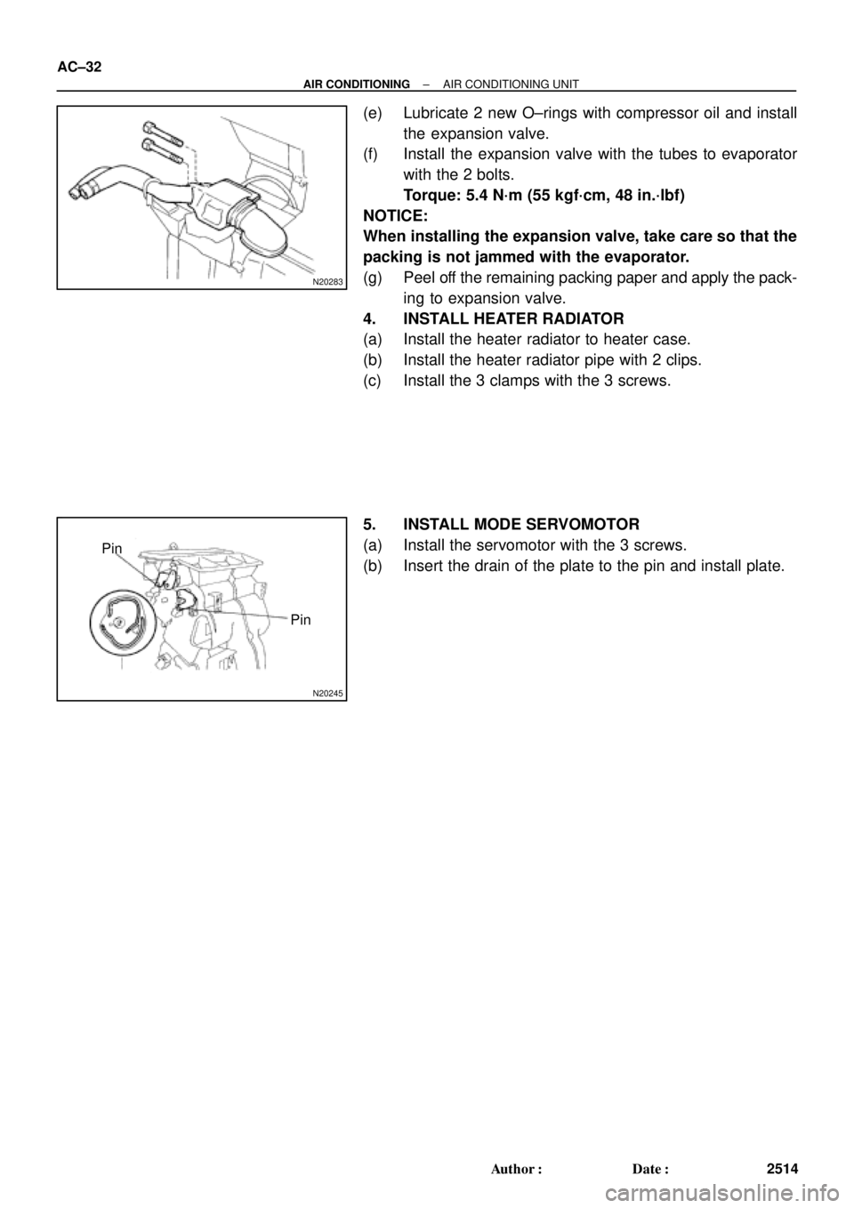
N20283
N20245
Pin
Pin AC±32
± AIR CONDITIONINGAIR CONDITIONING UNIT
2514 Author�: Date�:
(e) Lubricate 2 new O±rings with compressor oil and install
the expansion valve.
(f) Install the expansion valve with the tubes to evaporator
with the 2 bolts.
Torque: 5.4 N´m (55 kgf´cm, 48 in.´lbf)
NOTICE:
When installing the expansion valve, take care so that the
packing is not jammed with the evaporator.
(g) Peel off the remaining packing paper and apply the pack-
ing to expansion valve.
4. INSTALL HEATER RADIATOR
(a) Install the heater radiator to heater case.
(b) Install the heater radiator pipe with 2 clips.
(c) Install the 3 clamps with the 3 screws.
5. INSTALL MODE SERVOMOTOR
(a) Install the servomotor with the 3 screws.
(b) Insert the drain of the plate to the pin and install plate.
Page 1598 of 4770
AC0N8±02
AC±76
± AIR CONDITIONINGCONDENSER FAN
2558 Author�: Date�:
REMOVAL
1. 1MZ±FE engine models only:
DRAIN ENGINE COOLANT FROM RADIATOR
HINT:
It is not necessary to drain out all the coolant.
2. 1MZ±FE engine models only:
DISCONNECT UPPER RADIATOR HOSE
3. REMOVE CONDENSER FAN
(a) Disconnect the connector.
(b) Remove the 4 bolts and fan.
Page 1763 of 4770

14 (0.551)36 (1.417)
AT2711
Z10940
20
(0.787)mm (in.)
45
(1.772)50
(1.969)
AT3336
± AUTOMATIC TRANSAXLE (A140E)VALVE BODY ASSEMBLY
AX±5
1898 Author�: Date�:
V")
AX038±01
Q00073
AT0103
Z10944
mm (in.)
14 (0.551)36 (1.417)
AT2711
Z10940
20
(0.787)mm (in.)
45
(1.772)50
(1.969)
AT3336
± AUTOMATIC TRANSAXLE (A140E)VALVE BODY ASSEMBLY
AX±5
1898 Author�: Date�:
VALVE BODY ASSEMBLY
ON±VEHICLE REPAIR
1. DRAIN TRANSAXLE FLUID
2. REMOVE OIL PAN AND GASKET
NOTICE:
Some fluid will remain in the oil pan.
Remove the oil pan bolts, and carefully remove the oil pan as-
sembly. Discard the gasket.
3. EXAMINE PARTICLES IN PAN
Remove the magnets and use them to collect any steel chips.
Look carefully at the chips and particles in the pan and on the
magnet to anticipate what type of wear you will find in the trans-
axle.
�Steel (magnetic): bearing, gear and plate wear
�Brass (non±magnetic): bushing wear
4. REMOVE MANUAL VALVE BODY DETENT SPRING
AND MANUAL VALVE BODY
(a) Remove the detent spring on the manual valve body.
(b) Remove the manual valve body.
5. REMOVE OIL STRAINER AND OIL PIPE BRACKET
(a) Remove the 3 bolts and the oil strainer.
(b) Remove the 2 bolts and oil pipe bracket.
NOTICE:
Be careful as oil will come out of the strainer when it is re-
moved.
Page 1778 of 4770
AUTOMATIC TRANSAXLE UNIT
1913 Author�: Date�:
14. REMOVE EXHAUST MANIFOLD STAY
Remove the 2 bolts and exhaust manifold stay.
Torque: 42 N´m (")
Q10058
Q10059
Q00251
AX±20
± AUTOMATIC TRANSAXLE (A140E)AUTOMATIC TRANSAXLE UNIT
1913 Author�: Date�:
14. REMOVE EXHAUST MANIFOLD STAY
Remove the 2 bolts and exhaust manifold stay.
Torque: 42 N´m (430 kgf´cm, 31 ft´lbf)
15. REMOVE TRANSAXLE±TO±ENGINE BOLT
Torque: 66 N´m (670 kgf´cm, 48 ft´lbf)
16. REMOVE ENGINE HOOD
(a) Disconnect the washer pipe.
(b) Remove the 4 bolts and engine hood.
Torque: 14 N´m (145 kgf´cm, 10 ft´lbf)
17. RAISE AND SUPPORT VEHICLE SECURELY
18. REMOVE FRONT WHEELS
Torque: 103 N´m (1,050 kgf´cm, 76 ft´lbf)
19. REMOVE ENGINE UNDER COVER AND CENTER EN-
GINE UNDER COVER
20. DISCONNECT SHIFT CONTROL CABLE
(a) Remove the nut and disconnect the shift control cable
from the park/neutral position switch.
Torque: 15 N´m (150 kgf´cm, 11 ft´lbf)
(b) Remove the clip and disconnect the shift control cable
from the bracket.
21. REMOVE DIFFERENTIAL FLUID DRAIN PLUG AND
GASKET
HINT:
At the time of installation, please refer to the following item.
Replace the used gasket with a new gasket.
22. DRAIN DIFFERENTIAL FLUID
23. REMOVE LH AND RH FENDER APRON SEALS
24. REMOVE LH AND RH DRIVE SHAFTS
(See page SA±17)
Page 1804 of 4770
AUTOMATIC TRANSAXLEPREPARATION ±
AX±8
EQUIPMENT
Feeler gaugeCheck major clearance.
Vernier calipersCheck length of second coast
brake piston rod.
Dial indicator with magnetic baseCheck piston stroke and end play
of the output shaft.
Dial indicatorCheck inside diameter of
major bushing.
Straight edgeCheck side clearance of oil pump.
Torque wrench
LUBRICANT
ItemCapacityClassification
Automatic transaxle fluid:
Dry fill
Drain and refill
6.75 liters (7.10 US qts, 5.94 Imp.qts)
2.5 liters (2.6 US qts, 2.2 Imp.qts)
ATF D±@@@@@: [g 2] or
DEXRON®@@@@@: [g
3](DEXRON®@@@@@: [g 2])
Differential oil0.85 liters (0.89 US qts, 0.75 Imp.qts)
ATF D±@@@@@: [g 2] or
DEXRON®@@@@@: [g
3](DEXRON®@@@@@: [g 2])
SSM (SPECIAL SERVICE MATERIALS)
08826±00090Seal Packing 1281,
THREE BOND 1281 or equivalent
(FIPG)Differential LH bearing retainer
Differential RH retainer
08833±00070Adhesive 1324,
THREE BOND 1324 or equivalentDifferential RH retainer set bolt
AX02N±02
AX01V±08
AX02P±02
Page 1935 of 4770
VALVE BODY ASSEMBLY
AX±7
1927 Author�: Date�:
VALVE BODY ASSEMBLY
ON±VEHICLE REPAIR
1. DRAIN ATF
Using a hexagon wrench,")
AX03Q±02
AT3785
AT0103
D01019
Q05728
Connector
± AUTOMATIC TRANSAXLE (A541E)VALVE BODY ASSEMBLY
AX±7
1927 Author�: Date�:
VALVE BODY ASSEMBLY
ON±VEHICLE REPAIR
1. DRAIN ATF
Using a hexagon wrench, remove the drain plug and fluid into
the suitable container.
2. REMOVE OIL PAN AND GASKET
NOTICE:
Some fluid will remain in the oil pan.
Remove oil pan bolts, and carefully remove the pan assembly.
Discard the gasket.
3. EXAMINE PARTICLES IN PAN
Remove the magnets and use them to collect any steel chips.
Look at the chips and particles in the pan and magnet carefully
to anticipate what type of wear you will find in the transaxle.
�Steel (magnetic): bearing, gear and plate wear
�Brass (non±magnetic): bushing wear
4. REMOVE OIL STRAINER AND APPLY PIPE BRACKET
(a) Remove the 3 bolts and oil strainer.
NOTICE:
Be careful as oil will come out of the strainer when it is re-
moved.
(b) Remove the 3 bolts and apply pipe bracket.
5. REMOVE OIL PIPES
Pry up both pipe ends with a large screwdriver and remove the
5 pipes.
6. DISCONNECT SOLENOID CONNECTORS