Page 3990 of 4770
SS0AL±03
SS±28
± SERVICE SPECIFICATIONSLUBRICATION (5S±FE)
191 Author�: Date�:
TORQUE SPECIFICATION
Part tightenedN´mkgf´cmft´lbf
Oil pan x Drain plug3737527
Oil pump body cover x Oil pump body8.89078 in.´lbf
Oil pump x Cylinder block8.89078 in.´lbf
Oil strainer x Engine balancer5.45548 in.´lbf
Oil strainer x Oil pump5.45548 in.´lbf
Oil pan x Cylinder block5.45548 in.´lbf
Oil pan x Oil pump5.45548 in.´lbf
Oil cooler x Cylinder block Union bolt
Nut78.5
9.0800
9258
80 in.´lbf
Page 4011 of 4770
± SERVICE SPECIFICATIONSMANUAL TRANSAXLE (E153)
SS±49
212 Author�: Date�:
Transmission oil pump assembly x Transaxle case1717513
Transaxle case receiver x Transaxle case7.47565 in.´lbf
Clutch release fork support4748035
Control lever housing support bracket x Transaxle case1717513
Vehicle speed sensor1717513
Clutch release line bracket x Transaxle case1717513
Back±up light switch4041030
Filler and drain plug4950036
No.1 and No.2 oil receiver pipe x Transmission case1717513
Transmission oil cooler sub±assembly x Elbow3435025
Elbow x Transaxle case2727520
Transmission oil pump case x Oil pump cover101058
Transaxle case cover x Transaxle case5455040
Differential left case x Differential right case6364046
Ring gear set bolt1241,26091
Page 4017 of 4770

SS±55
218 Author�: Date�:
TORQUE SPECIFICATION
Part tightenedN´mkgf´cmft´lbf
Transaxle x Starter4243031
Transaxle x Rear end plate252")
SS0AT±01
± SERVICE SPECIFICATIONSAUTOMATIC TRANSAXLE (A140E)
SS±55
218 Author�: Date�:
TORQUE SPECIFICATION
Part tightenedN´mkgf´cmft´lbf
Transaxle x Starter4243031
Transaxle x Rear end plate2525018
Transaxle x No.1 exhaust pipe support bracket1919514
Transaxle x Engine6667048
Torque converter clutch x Drive plate2728020
Body x Front lower brace Bolt
Nut181
361,850
370134
27
Body x Rear lower brace 19 mm head bolt
14 mm head bolt
Nut181
32
361,850
330
370134
24
27
Front suspension member x FR engine mounting TMC made
TMMK made: Green color bolt
TMMK made: Silver color bolt80
66
44820
670
45059
48
32
Front suspension member x RR engine mounting6667048
Front suspension member x LH engine mounting8082059
Transaxle x LH engine mounting6465047
Front suspension member x Steering return pipe mounting bracket101007
Front suspension member x Stabilizer bar bracket1919514
Stabilizer bar x Stabilizer bar link3940029
Ball joint x Lower suspension arm1271,30094
Steering gear housing set bolt x Nut1811,850134
Exhaust manifold x Front exhaust pipe6263046
Front suspension member x Exhaust pipe No.1 support bracket3333024
Front exhaust pipe x Center exhaust pipe5657041
No.1 exhaust pipe support bracket x Exhaust pipe clamp3333024
Axle hub nut2943,000217
Steering knuckle x Tie rod end4950036
Vehicle speed sensor x Transaxle1616012
Park/neutral position switch x Transaxle Bolt
Nut5.4
6.955
7048 in.´lbf
61 in.´lbf
Park/neutral position switch x Control shaft lever131309
Control shaft lever x Control cable1515011
Oil pan x Drain plug4950036
Oil pan x Transaxle4.95043 in.´lbf
Valve body x Manual valve body101007
Valve body x Transaxle101007
Drive shaft center bearing lock bolt3233024
Stiffener plate Front side
Rear side42
39430
40031
29
Exhaust manifold stay Front side
Rear side42
39430
40031
29
Page 4019 of 4770

SS±57
220 Author�: Date�:
TORQUE SPECIFICATION
Part tightenedN´mkgf´cmft´lbf
Front engine front mounting insulator x Front frame asse")
SS0BM±01
± SERVICE SPECIFICATIONSAUTOMATIC TRANSAXLE (A541E)
SS±57
220 Author�: Date�:
TORQUE SPECIFICATION
Part tightenedN´mkgf´cmft´lbf
Front engine front mounting insulator x Front frame assemblyTMC:
TMMK:
Green color bolt
Silver color bolt80
66
44820
670
45059
48
32
Rear engine mounting insulator x Front frame assembly8082059
LH transaxle mounting insulator x Transaxle6465047
Engine mounting absorber x Front frame assembly4849035
Transaxle x Engine 17 mm bolt6667048
Transaxle x Engine 12 mm bolt4849035
Torque converter clutch x Drive plate4142030
Valve body x Transaxle case1111 08
Oil strainer x Valve body1111 08
Oil pan x Transaxle case7.88069 in.´lbf
Oil pan drain plug4950036
Park/Neutral position switch x Transaxle case (bolt)5.45548 in.´lbf
Park/Neutral position switch (nut)6.97061 in.´lbf
B3 apply pipe retainer1111 08
Connector clamp1111 08
Manual valve body x Transaxle case1111 08
Detent spring x Manual valve body1111 08
Oil pipe bracket101007
Steering gear housing x Front suspension member1811,850134
Stabilizer bar bracket1919514
Vehicle speed sensor x Transaxle case4.95043 in.´lbf
Direct clutch speed sensor x Transaxle case1111 08
Transfer lubrication apply pipe retainer1111 08
Exhaust manifold bracket x Transaxle case Except California
California20
34200
35014
25
Exhaust manifold plate Except California
California20
34200
35014
25
Front frame x Body 19 mm1811,850134
Front frame x Body 14 mm3233024
Front frame x Body Nut3637027
Exhaust front pipe x Exhaust center pipe5657041
Exhaust manifold x Exhaust front pipe6263046
Exhaust front pipe support stay x Exhaust front pipe support bracket3333024
Exhaust pipe support x Front frame3333024
Starter x Torque converter clutch housing3940029
Transaxle control shaft lever x Park/neutral position switch1515011
Throttle cable adjusting nut1515011
Drive plate x Crankshaft8385061
Shift control cable x Transaxle control shaft lever1515011
Throttle cable retaining plate set bolt5.45548 in.´lbf
Shift solenoid valve No.1, No.2, SL, SLN x Valve body6.66758 in.´lbf
Page 4066 of 4770
SF0DP±03
B01283
S05534
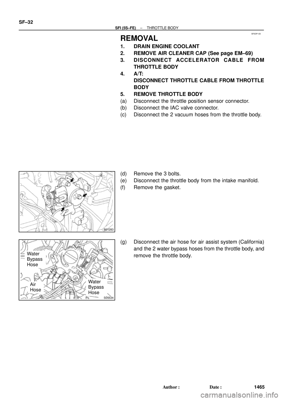
Water
Bypass
Hose
Water
Bypass
HoseAir
Hose SF±32
± SFI (5S±FE)THROTTLE BODY
1465 Author�: Date�:
REMOVAL
1. DRAIN ENGINE COOLANT
2. REMOVE AIR CLEANER CAP (See page EM±69)
3. DISCONNECT ACCELERATOR CABLE FROM
THROTTLE BODY
4. A/T:
DISCONNECT THROTTLE CABLE FROM THROTTLE
BODY
5. REMOVE THROTTLE BODY
(a) Disconnect the throttle position sensor connector.
(b) Disconnect the IAC valve connector.
(c) Disconnect the 2 vacuum hoses from the throttle body.
(d) Remove the 3 bolts.
(e) Disconnect the throttle body from the intake manifold.
(f) Remove the gasket.
(g) Disconnect the air hose for air assist system (California)
and the 2 water bypass hoses from the throttle body, and
remove the throttle body.
Page 4139 of 4770
SF07V±03
S04506
S06123
(a)
(b)
(d) (e)
(c)
S04527
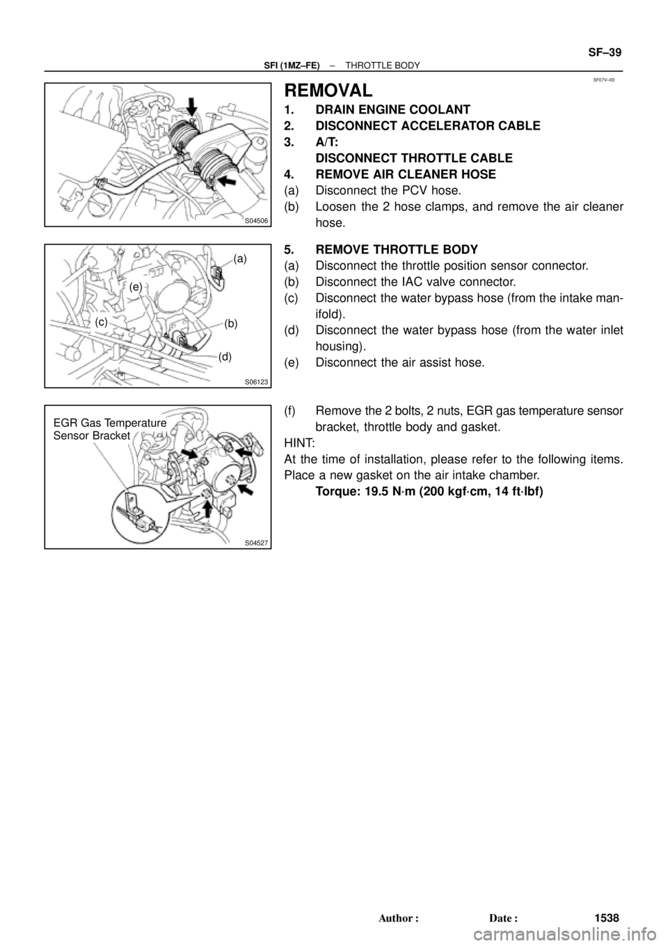
EGR Gas Temperature
Sensor Bracket
± SFI (1MZ±FE)THROTTLE BODY
SF±39
1538 Author�: Date�:
REMOVAL
1. DRAIN ENGINE COOLANT
2. DISCONNECT ACCELERATOR CABLE
3. A/T:
DISCONNECT THROTTLE CABLE
4. REMOVE AIR CLEANER HOSE
(a) Disconnect the PCV hose.
(b) Loosen the 2 hose clamps, and remove the air cleaner
hose.
5. REMOVE THROTTLE BODY
(a) Disconnect the throttle position sensor connector.
(b) Disconnect the IAC valve connector.
(c) Disconnect the water bypass hose (from the intake man-
ifold).
(d) Disconnect the water bypass hose (from the water inlet
housing).
(e) Disconnect the air assist hose.
(f) Remove the 2 bolts, 2 nuts, EGR gas temperature sensor
bracket, throttle body and gasket.
HINT:
At the time of installation, please refer to the following items.
Place a new gasket on the air intake chamber.
Torque: 19.5 N´m (200 kgf´cm, 14 ft´lbf)
Page 4495 of 4770
SLIDING ROOF DIAGNOSTIC TIPS ± BO020-01 August 17, 2001
Page 2 of 7
REFPART NUMBERPART NAMEQTY
1963287±AA010Cap, Sliding Roof Housing Drain End, RH1
2063288±AA010Cap, Sliding Roof Housing Drain End, LH1
2163306±AA010±A1/B1/G1Trim Sub±Assy, Sliding Shade1
2290080±11209Bolt, With Washer8
2390084±14004Screw, Hex Lobular2
2490084±15005Screw, With Washer4
2590084±16013Screw, Hex Lobular Tapping (Long)2
2690084±16014Screw, Hex Lobular Tapping (Short) (Not Illustrated)2
2790084±26003Rivet6
2890084±53003Fastener, Hook3
2990159±60545Screw, With Washer Tapping (Ground Wire)1
3090179±06069Nut6
1
17 24
3 25
11
124
21 8 7
14 13
910
5
6
23
Parts
Information
(Continued)