Page 3366 of 4770
EVAPORATIVE EMISSION (EVAP) CONTROL")
B01252
AirDisconnect
Air Inlet Line Hose
B01253
Pinch
Push
AA
Pinch
B01148
B01149
Air
Purge Port
Vent Port
Air Drain Port
Cap
EVAP
Port
± EMISSION CONTROL (5S±FE)EVAPORATIVE EMISSION (EVAP) CONTROL SYSTEM
EC±9
1407 Author�: Date�:
HINT:
In the condition that the fuel fuel is full, as the float value of the
fill check valve is closed and has no ventilation, it is necessary
to check the fuel amount (volume).
(d) Check if there is any struck in the vent line hose and EVAP
line hose.
If there is no stuck in hoses, replace the fuel cutoff valve and fill
check valve.
(e) Reconnect the purge line hose and EVAP line hose to the
charcoal canister.
7. CHECK AIR INLET LINE
(a) Disconnect the air inlet line hose from the charcoal canis-
ter.
(b) Check that there is ventilation in the air inlet line.
(c) Reconnect the air inlet line hose to the charcoal canister.
8. REMOVE CHARCOAL CANISTER ASSEMBLY
(a) Disconnect the VSV connector.
(b) Disconnect the vapor pressure sensor connector.
(c) Disconnect the purge line hose, EVAP line hose and air
inlet line hose from the charcoal canister.
(d) Disconnect the vent line hose from the charcoal canister.
(1) Push the connector deep inside.
(2) Pinch portion A.
(3) Pull out the connector.
(e) Remove the 2 charcoal canister mounting bolts.
(f) Remove the vapor pressure sensor mounting bolt.
(g) Remove the charcoal canister assembly.
9. INSPECT CHARCOAL CANISTER
(a) Visually check the charcoal canister for cracks or dam-
age.
(b) Inspect the charcoal canister operation.
(1) Plug the vent port with a cap.
(2) While holding the purge port closed, blow air (1.76
kPa, 18 gf/cm
2, 0.26 psi) into the EVAP port and
check that air flows from the air drain port.
Page 3383 of 4770
EVAPORATIVE EMISSION (EVAP) CONTROL")
B01252
AirDisconnect
Air Inlet Line Hose
B01253
Pinch
Push
AA
Pinch
B01148
B01149
Air
Purge Port
Vent Port
Air Drain Port
Cap
EVAP
Port
± EMISSION CONTROL (1MZ±FE)EVAPORATIVE EMISSION (EVAP) CONTROL SYSTEM
EC±9
1424 Author�: Date�:
HINT:
In the condition that the fuel fuel is full, as the float value of the
fill check valve is closed and has no ventilation, it is necessary
to check the fuel amount (volume).
(d) Check if there is any struck in the vent line hose and EVAP
line hose.
If there is no stuck in hoses, replace the fuel cutoff valve and fill
check valve.
(e) Reconnect the purge line hose and EVAP line hose to the
charcoal canister.
7. CHECK AIR INLET LINE
(a) Disconnect the air inlet line hose from the charcoal canis-
ter.
(b) Check that there is ventilation in the air inlet line.
(c) Reconnect the air inlet line hose to the charcoal canister.
8. REMOVE CHARCOAL CANISTER ASSEMBLY
(a) Disconnect the VSV connector.
(b) Disconnect the vapor pressure sensor connector.
(c) Disconnect the purge line hose, EVAP line hose and air
inlet line hose from the charcoal canister.
(d) Disconnect the vent line hose from the charcoal canister.
(1) Push the connector deep inside.
(2) Pinch portion A.
(3) Pull out the connector.
(e) Remove the 2 charcoal canister mounting bolts.
(f) Remove the vapor pressure sensor mounting bolt.
(g) Remove the charcoal canister assembly.
9. INSPECT CHARCOAL CANISTER
(a) Visually check the charcoal canister for cracks or dam-
age.
(b) Inspect the charcoal canister operation.
(1) Plug the vent port with a cap.
(2) While holding the purge port closed, blow air (1.76
kPa, 18 gf/cm
2, 0.26 psi) into the EVAP port and
check that air flows from the air drain port.
Page 3425 of 4770
EM0YL±01
S05282
S05281
S05300
TMC
Made
TMMK
Made
S05297
Clamp
Sensor
Connector
± ENGINE MECHANICAL (5S±FE)CYLINDER HEAD
EM±33
1205 Author�: Date�:
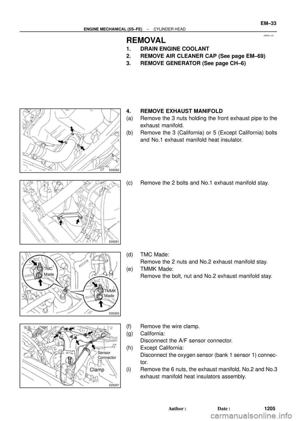
REMOVAL
1. DRAIN ENGINE COOLANT
2. REMOVE AIR CLEANER CAP (See page EM±69)
3. REMOVE GENERATOR (See page CH±6)
4. REMOVE EXHAUST MANIFOLD
(a) Remove the 3 nuts holding the front exhaust pipe to the
exhaust manifold.
(b) Remove the 3 (California) or 5 (Except California) bolts
and No.1 exhaust manifold heat insulator.
(c) Remove the 2 bolts and No.1 exhaust manifold stay.
(d) TMC Made:
Remove the 2 nuts and No.2 exhaust manifold stay.
(e) TMMK Made:
Remove the bolt, nut and No.2 exhaust manifold stay.
(f) Remove the wire clamp.
(g) California:
Disconnect the A/F sensor connector.
(h) Except California:
Disconnect the oxygen sensor (bank 1 sensor 1) connec-
tor.
(i) Remove the 6 nuts, the exhaust manifold, No.2 and No.3
exhaust manifold heat insulators assembly.
Page 3461 of 4770
ENGINE UNIT
EM±69
1241 Author�: Date�:
REMOVAL
1. REMOVE HOOD
2. REMOVE FRONT FENDER APRON SEALS
3. DRAIN ENGINE COOLANT
4. DRAIN ENGINE OIL
5. DISCONNEC")
EM08F±04
S05251
± ENGINE MECHANICAL (5S±FE)ENGINE UNIT
EM±69
1241 Author�: Date�:
REMOVAL
1. REMOVE HOOD
2. REMOVE FRONT FENDER APRON SEALS
3. DRAIN ENGINE COOLANT
4. DRAIN ENGINE OIL
5. DISCONNECT ACCELERATOR CABLE
6. REMOVE AIR CLEANER CAP
(a) Disconnect the IAT sensor connector.
(b) Disconnect the VSV connector for the EVAP
(c) Disconnect the PCV hose from the cylinder head cover.
(d) Disconnect the EVAP hose from the throttle body.
(e) Disconnect the EVAP hose from the VSV.
(f) Disconnect the 2 clamps, and disconnect the air cleaner
cap from the air cleaner case.
(g) Loosen hose clamp, and disconnect the air cleaner hose
from the throttle body.
(h) Remove the air cleaner cap and hose assembly.
7. REMOVE AIR CLEANER CASE
(a) Remove the air filter.
(b) Remove the 3 bolts and air cleaner case.
8. REMOVE BATTERY AND TRAY
9. REMOVE CRUISE CONTROL ACTUATOR
10. REMOVE RADIATOR (See page CO±18)
11. REMOVE FRONT EXHAUST PIPE
(a) Remove the 2 bolts holding the support stay to the sup-
port bracket.
(b) Remove the 2 bolts holding the support bracket to the
front frame.
(c) Remove the 2 bolts and 2 nuts holding the front exhaust
pipe to the center exhaust pipe.
(d) Remove the 3 nuts holding the front exhaust pipe to the
exhaust manifold.
(e) Remove the front exhaust pipe and 2 gaskets.
(f) Remove the nut and support bracket.
12. DISCONNECT CONNECTORS, WIRES, CABLES,
CLAMPS AND HOSES
(a) Disconnect the generator wire.
(b) Disconnect the generator connector.
(c) Disconnect the wire clamp from the generator.
(d) Disconnect the starter cable.
(e) Disconnect the starter connector.
(f) Disconnect the DLC1 from the bracket.
Page 3476 of 4770
A07367
Water Pump, Water Bypass Pipe
and Oil Cooler Assembly
Water Pump and Water
Bypass Pipe Assembly
(w/o Oil Cooler)
Union Bolt
Generator Drive Belt Adjusting Bar
Knock Sensor 1Oil Filter
Oil Dipstick
PS Pump
Bracket
Crankshaft Position Sensor Connector
Oil Pump
� Gasket x 10
Oil Strainer
Oil Pan
Drain Plug
N´m (kgf´cm, ft´lbf)
� Non±reusable partx 17 � Gasket
� Gasket � O±Ring
8.8 (90, 78 in.´lbf)5.4 (55, 48 in.´lbf)
5.4 (55, 48 in.´lbf)
� O±Ring
78.5 (800, 58)
w/ Oil Cooler
: Specified torque
Crankshaft
Front Oil
Seal �
EM±84
± ENGINE MECHANICAL (5S±FE)CYLINDER BLOCK
1256 Author�: Date�:
Page 3577 of 4770
ENGINE UNIT
EM±71
1357 Author�: Date�:
REMOVAL
1. REMOVE BATTERY AND TRAY
2. REMOVE HOOD
3. REMOVE ENGINE FENDER APRON SEALS
4. DRAIN ENGINE COOLANT
5.")
EM04Y±03
S05048
± ENGINE MECHANICAL (1MZ±FE)ENGINE UNIT
EM±71
1357 Author�: Date�:
REMOVAL
1. REMOVE BATTERY AND TRAY
2. REMOVE HOOD
3. REMOVE ENGINE FENDER APRON SEALS
4. DRAIN ENGINE COOLANT
5. DRAIN ENGINE OIL
6. DISCONNECT ACCELERATOR CABLE
7. REMOVE AIR CLEANER CAP ASSEMBLY AND AIR
CLEANER CASE
8. REMOVE CRUISE CONTROL ACTUATOR
9. REMOVE RADIATOR (See page CO±18)
10. REMOVE FRONT EXHAUST PIPE
(a) Remove the 2 bolts holding the support stay to the sup-
port bracket.
(b) Remove the 2 bolts holding the support bracket to the
front frame.
(c) Remove the 2 bolts and 2 nuts holding the front exhaust
pipe to the center exhaust pipe.
(d) Remove the 4 nuts holding the front exhaust pipe to the
exhaust manifolds.
(e) Remove the front exhaust pipe and 3 gaskets.
11. DISCONNECT CONNECTORS, CABLE, CLAMPS
AND HOSES
(a) Disconnect the igniter connector on the LH fender apron.
(b) Disconnect the noise filter connector on the LH fender
apron.
(c) Disconnect the generator wire and connector.
(d) Disconnect the starter wire and connector.
(e) Disconnect the 2 ground strap connectors from the LH
fender apron.
(f) Disconnect the 2 ground strap connectors from the RH
fender apron.
(g) Disconnect the ground cable from the battery body brack-
et.
(h) Disconnect the engine wire protector clamp from the bat-
tery body bracket.
(i) Disconnect the engine wire clamp from the bracket on the
RH fender apron.
(j) Disconnect the engine wire clamp from the bracket on the
fuel filter.
Page 3590 of 4770
CYLINDER BLOCK
1370 Author�: Date�:
11. REMOVE WATER I")
P18762
P18763
WaterSeal
Plate
Oil Filter
Union
12 mm
Hexagon
Wrench
Coolant
Drain
Union
P12410
P12508
P12695
EM±84
± ENGINE MECHANICAL (1MZ±FE)CYLINDER BLOCK
1370 Author�: Date�:
11. REMOVE WATER INLET HOUSING
(a) Remove the engine wire band.
(b) Disconnect the engine wire clamp from the bracket.
(c) Remove the 8 bolts, 2 nuts and water inlet housing.
12. REMOVE WATER PUMP (See page CO±6)
13. REMOVE NO.2 OIL PAN (See page LU±9)
14. REMOVE OIL STRAINER (See page LU±9)
15. REMOVE NO.1 OIL PAN (See page LU±9)
16. REMOVE OIL PUMP (See page LU±9)
17. REMOVE OIL FILTER (See page LU±9)
18. REMOVE OIL FILTER UNION
Using a 12 mm hexagon wrench, remove the oil filter union.
19. REMOVE WATER SEAL PLATE
Remove the 2 nuts and seal plate.
20. REMOVE ENGINE COOLANT DRAIN UNION
21. REMOVE EGR COOLER
Remove the 3 bolts, 2 nuts, EGR cooler and gasket.
22. REMOVE REAR OIL SEAL RETAINER
(a) Remove the 6 bolts.
(b) Using a screwdriver, remove the oil seal retainer by prying
the portions between the oil seal retainer and main bear-
ing cap.
23. CHECK CONNECTING ROD THRUST CLEARANCE
Using a dial indicator, measure the thrust clearance while mov-
ing the connecting rod back and forth.
Standard thrust clearance:
0.15 ± 0.30 mm (0.0059 ± 0.0118 in.)
Maximum thrust clearance: 0.35 mm (0.0138 in.)
If the thrust clearance is greater than maximum, replace the
connecting rod assembly(s). If necessary, replace the crank-
shaft.
Page 3721 of 4770
OIL PUMP
LU±7
1653 Author�: Date�:
REMOVAL
HINT:
When repairing the oil pump, the oil pan and strainer should be
removed and cleaned.
1.")
LU03K±03
S05311
S05952
SST
SST
S05928
± LUBRICATION (5S±FE)OIL PUMP
LU±7
1653 Author�: Date�:
REMOVAL
HINT:
When repairing the oil pump, the oil pan and strainer should be
removed and cleaned.
1. DRAIN ENGINE OIL
2. REMOVE FRONT EXHAUST PIPE (See page EM±69)
3. REMOVE NO.2 EXHAUST MANIFOLD STAY AND LH
STIFFENER PLATE (See page EM±69)
4. REMOVE EXHAUST PIPE BRACKET, OIL PAN INSU-
LATOR AND NO.2 REAR END PLATE
(See page EM±69)
5. REMOVE OIL PAN
(a) Remove the oil dipstick.
(b) Remove the 17 bolts and 2 nuts.
(c) Insert the blade of SST between the cylinder block and oil
pan, and cut off applied sealer and remove the oil pan.
SST 09032±00100
NOTICE:
�Do not use SST for the oil pump body side and rear oil
seal retainer.
�Be careful not to damage the oil pan flange.
6. REMOVE OIL STRAINER
Remove the bolt, 2 nuts, oil strainer and gasket.
7. REMOVE TIMING BELT (See page EM±17)
8. REMOVE NO.2 IDLER PULLEY
Remove the bolt and idler pulley.
9. REMOVE CRANKSHAFT TIMING PULLEY
(See page EM±17)
10. REMOVE OIL PUMP PULLEY (See page EM±17)

Union Bolt
Generator Drive Belt Adjusting Bar
Knock Sensor 1Oil Filter
Oil Dipst")