Page 1399 of 4770
SHIFT LOCK
1T 11D81C7
1H 21R 4
1 2STOP LI GH T
SW 15A
CIG15A
EC U± IG15A
STOP
G±WP±L
B±R
13 6
KEY INTERLOCK
SOLENOID
L±B W±B
W± B W±B
5 4SHIFT LOCK ECU
SHIFT LOCK
CONTROL SW
SHIFT LOCK
SOLENOID
L±B
B±R P±L
A
AJUNCTION
CONNECTOR
G
G±WG± R
L
L±R
A
A
IG IFJUNCTION
CONNECTOR FROM POWER SOURCE SYSTEM (
SEE PAGE 50)
J 6S 6
S 3
K 3J 5
W G± W
P1
P
P2
SLS±
SLS+2 1 2 3
1
KLS+E ACC IG STPC
C
IG1 5
1J7
1J8
A
A AW± B W±B
JUNCTION
CONNECTOR
JUNCTION
CONNECTOR J 7J1 1JUNCTION
CONNECTOR J161 2
Page 1400 of 4770

When the ignition SW is turned to ACC position the current from the CIG fuse flows to TERMINAL 1 of the shift lock ECU, in
the ON position, the current from the ECU±IG fuse flows to TERMINAL 3 of the ECU.
1. SHIFT LOCK MECHANISM
With the ignition SW on, when a signal that the brake pedal is depressed (Stop light SW on) and a signal that the shift lever
is put in P position (Continuity between P1 and P of the shift lock control SW) is input to the shift lock ECU, the ECU
operates and current flows from TERMINAL 3 of the ECU to TERMINAL SLS+ of the shift lock solenoid to solenoid to
TERMINAL SLS± to TERMINAL 5 of the ECU to GROUND. This causes the shift lock solenoid to turn on (Plate stopper
disengages) and the shift lever can shift into position other than the P.
2. KEY INTERLOCK MECHANISM
With the ignition SW ON or ACC position, when the shift lever is put in P position (No continuity between P2 and P of shift
lock control SW), the current flowing from TERMINAL 4 of the shift lock ECU to the key interlock solenoid is cut off. This
causes the key interlock solenoid to turn off (Lock lever disengages from LOCK position) and the ignition key can be turned
from ACC to LOCK position.
S3 SHIFT LOCK ECU
1±GROUND : Approx. 12 volts with the ignition SW at ACC or ON position
3±GROUND : Approx. 12 volts with the ignition SW at ON position
5±GROUND : Always continuity
6±GROUND : Approx. 12 volts with the brake pedal depressed
S6 STOP LIGHT SW
2±1 : Closed with the brake pedal depressed
: PARTS LOCATION
CodeSee PageCodeSee PageCodeSee Page
J531J1131S331
J631J1631S631
J731K331
: JUNCTION BLOCK AND WIRE HARNESS CONNECTOR
CodeSee PageJunction Block and Wire Harness (Connector Location)
1C20Cowl Wire and Instrument Panel J/B (Lower Finish Panel)
1D20Instrument Panel Wire and Instrument Panel J/B (Lower Finish Panel)1H20Instrument Panel Wire and Instrument Panel J/B (Lower Finish Panel)
1J20Cowl Wire and Instrument Panel J/B (Lower Finish Panel)1R20Cowl Wire and Instrument Panel J/B (Lower Finish Panel)
1T20Instrument Panel Wire and Instrument Panel J/B (Lower Finish Panel)
: CONNECTOR JOINING WIRE HARNESS AND WIRE HARNESS
CodeSee PageJoining Wire Harness and Wire Harness (Connector Location)
IG140Instrument Panel Wire and Cowl Wire (Lower Finish Panel)
: GROUND POINTS
CodeSee PageGround Points Location
IF40Left Kick Panel
IG40Instrument Panel Brace LH
SYSTEM OUTLINE
SERVICE HINTS
Page 1513 of 4770

L PART NUMBER OF CONNECTORS
Code Part Name Part NumberCodePart Name Part Number
Note : Not all of the above part numbers of the connector are established for the supply. In case of ordering
a connector or terminal with wire, please confirm in advance if there is supply for it using ªParts Catalog
Newsº (published by Parts Engineering Administration Dept.).
J15Junction Connector90980±10803
J16Junction Connector90980±11661J17Junction Connector90980±11661
J18Junction Connector90980±11542J19Junction Connector90980±11542
J20Junction Connector90980±11539
J21Junction Connector90980±11542
J22Junction Connector90980±11539J23Junction Connector90980±11539
J24Junction Connector
J25Junction Connector90980±11529
J26Junction Connector
J27Junction Connector90980±11661J28Junction Connector90980±11661
J29Junction Connector90980±11502
J30Junction Connector90980±11661J31Junction Connector90980±11661
J32Junction Connector90980±10803
J33Junction Connector
J34Junction Connector90980±11661J35Junction Connector90980±11661
J36Junction Connector
J37Junction Connector90980±11542
J38Junction Connector90980±10803J39Junction Connector90980±10803
J40Junction Connector90980±10976
K 1Knock Sensor 190980±11166K 2Knock Sensor 290980±11166
K 3Key Interlock Solenoid90980±10825
L 1License Plate Light LH90980±11148L 2License Plate Light RH90980±11148
L 3Light Failure Sensor90980±10803
L 4Luggage Compartment Key Unlock SW90980±11212
L 5Luggage Compartment Light90980±11148
L 6Luggage Compartment Light SW90980±11097
M 1Manifold Absolute Pressure Sensor90980±10845
M 2Mass Air Flow Meter90980±11317
M 3Moon Roof Control SW and Relay90980±10799
M 4Moon Roof Motor and Limit SW90980±11011
N 1Noise Filter (Ignition)90980±10843
N 2Noise Filter (Rear Window Defogger)90980±11259
O 1Oil Pressure SW90980±11363
O 2O/D Main SW and A/T Shift Lever
Illumination90980±10795
P 1Park/Neutral Position SW,A/T Indicator Light
SW and Back±Up Light SW90980±11332
P 2Power Steering Oil Pressure SW90980±11428
P 3Parking Brake SW90980±10871
P 4Power Outlet90980±10760
P 5Personal Light90980±10825
P 6Power Window Control SW Front RH90980±10789
P 7Power Window Control SW Rear LH90980±10631P 8Power Window Control SW Rear RH90980±10631
P 9Power Window Master SW and Door Lock
Control SW LH90980±10807
P10Power Window Motor Front LH
P11Power Window Motor Front RH90980±10860P12Power Window Motor Rear LH90980±10860
P13Power Window Motor Rear RH
P14Power Seat Control SW (Driver's Seat)
P15Power Seat Control SW
(Front Passenger's Seat)90980±10803
P16Power Seat Motor
(Driver's Seat Rear Vertical Control)
P17Power Seat Motor
(Driver's Seat Reclining Control)90980±10825
P18Power Seat Motor
(Driver's Seat Slide Control)
P19Power Seat Motors (Driver's Seat)90980±11001
P20Power Seat Motor (Front Passenger's Seat
Rear Vertical Control)
P21Power Seat Motor (Front Passenger's Seat
Reclining Control)90980±10825
P22Power Seat Motor (Front Passenger's Seat
Slide Control)
P23Power Seat Motors
(Front Passenger's Seat)90980±11001
P24Pretensioner LH90980±11862P25Pretensioner RH90980±11862
R 1Radiator Fan Motor90980±10928
R 2Radio and Player90980±10996
R 3Radio and Player90980±10997
R 4Radio and Player90980±11264
R 5Rear Window Defogger SW90980±11280
R 6Remote Control Mirror SW90980±11450
R 7Rheostat90980±10908
R 8Rear Combination Light LH90980±10795
R 9Rear Combination Light LH90980±11001
R10Rear Combination Light RH90980±10795
R11Rear Combination Light RH90980±11001
Page 1639 of 4770
AUTOMATIC TRANSAXLEOPERATION ±
AX±6
2. HYDRAULIC CONTROL SYSTEM
The hydraulic control system is composed of the oil pump, the valve body, the solenoid valves, the accu-
mulators, the clutches and brakes, and the governor valve as well as the fluid passages which connect
all of these components.
Based on the hydraulic pressure created by the oil pump, the hydraulic control system governs the hy-
draulic pressure acting on the torque converter clutch, clutches and brakes in accordance with the ve-
hicle driving conditions.
There are three solenoid valves on the valve body.
The No.1 and No.2 solenoid valves are turned on and off by signals from the ECM to operate the shift
valves and change the gear shift position.
The No.3 solenoid valve is operated by signals from the ECM to engage or disengage the lock±up
clutch of the torque converter.
Page 1640 of 4770
AUTOMATIC TRANSAXLEOPERATION ±
AX±7
2. ELECTRONIC CONTROL SYSTEM
The electronic control system for controlling the shift timing and the operation of the lock±up clutch is
composed of the following 3 parts:
(a) Sensors: These sense the vehicle speed and throttle position and send this data to the ECM in the form
of electronic signals.
(b) ECM: This determines the shift and lock±up timing based upon the signals from the sensors.
(c) Actuators: Solenoid valves divert hydraulic pressure from one circuit of the hydraulic control unit to
another, thus controlling shifting and lock±up timing.
Page 1648 of 4770
AUTOMATIC TRANSAXLECOMPONENT PARTS REMOVAL ±
AX±15
SEPARATE BASIC SUBASSEMBLY
1. REMOVE PARK/NEUTRAL POSITION SWITCH
(a) Remove the manual shift lever.
(b) Pry off the lock washer and remove the manual valve
shaft nut.
(c) Remove the 2 bolts and pull out the park/neutral position
switch.
2. REMOVE UNION AND ELBOW
(a) Using the open end wrench, remove the union and elbow.
(b) Remove the O±rings from the union and elbow.
3. REMOVE SL SOLENOID
(a) Disconnect the connector.
(b) Remove the 2 bolts and SL solenoid.
4. REMOVE THROTTLE CABLE RETAINING PLATE
5. REMOVE SOLENOID WIRE RETAINING BOLT
6. REMOVE COVER
(a) Remove the 2 bolts and cover bracket.
AX0EW±02
Page 1764 of 4770
Z10941 AT0493
AT7868
AT0399
OR0038
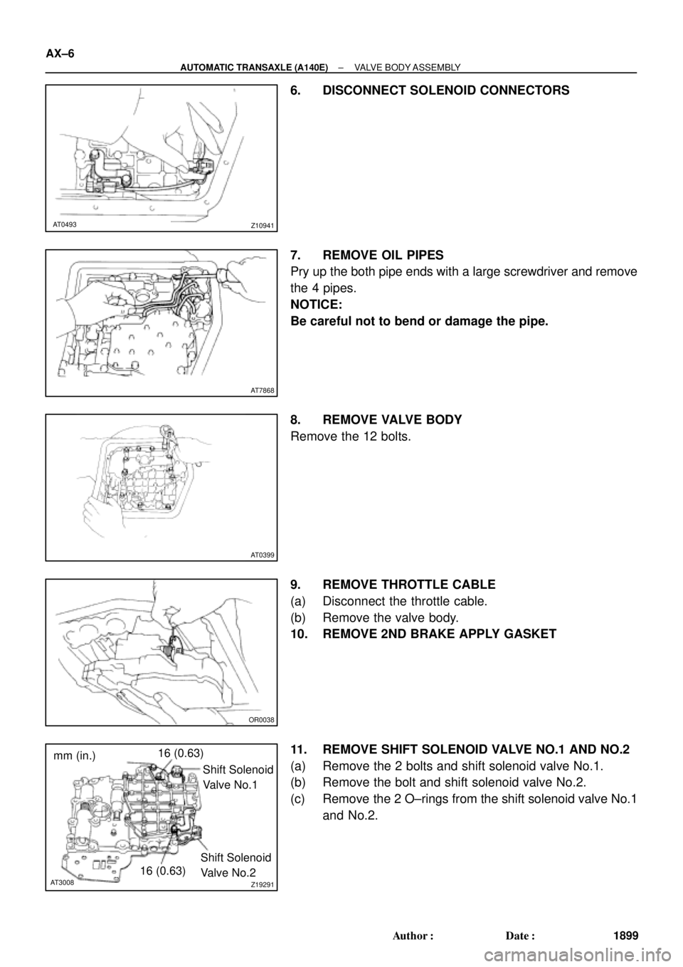
Z19291
16 (0.63)
Shift Solenoid
Valve No.1
16 (0.63)Shift Solenoid
Valve No.2
AT3008
mm (in.) AX±6
± AUTOMATIC TRANSAXLE (A140E)VALVE BODY ASSEMBLY
1899 Author�: Date�:
6. DISCONNECT SOLENOID CONNECTORS
7. REMOVE OIL PIPES
Pry up the both pipe ends with a large screwdriver and remove
the 4 pipes.
NOTICE:
Be careful not to bend or damage the pipe.
8. REMOVE VALVE BODY
Remove the 12 bolts.
9. REMOVE THROTTLE CABLE
(a) Disconnect the throttle cable.
(b) Remove the valve body.
10. REMOVE 2ND BRAKE APPLY GASKET
11. REMOVE SHIFT SOLENOID VALVE NO.1 AND NO.2
(a) Remove the 2 bolts and shift solenoid valve No.1.
(b) Remove the bolt and shift solenoid valve No.2.
(c) Remove the 2 O±rings from the shift solenoid valve No.1
and No.2.
Page 1765 of 4770
VALVE BODY ASSEMBLY
AX±7
1900 Author�: Date�:
12. I")
OR0038
Z10942
C
DB
A
CBA B
AT0492
AT7870
Z10941 AT0493
Shift Solenoid Valve No.2
BlackWhite
Shift Solenoid Valve No.1
± AUTOMATIC TRANSAXLE (A140E)VALVE BODY ASSEMBLY
AX±7
1900 Author�: Date�:
12. INSTALL SHIFT SOLENOID VALVE NO.1 AND NO.2
(a) Coat 2 new O±rings with ATF.
(b) Install the 2 O±rings to the shift solenoid valve No.1 and
No.2.
(c) Install the shift valve No.1 with the 2 bolts.
Torque: 5.4 N´m (55 kgf´cm, 48 in.´lbf)
(d) Install the shift valve No.2 with the bolt.
Torque: 5.4 N´m (55 kgf´cm, 48 in.´lbf)
13. INSTALL NEW 2ND BRAKE APPLY GASKET
14. INSTALL VALVE BODY
(a) While holding the cam down by your hand, slip the cable
end into the slot.
NOTICE:
Do not entangle the solenoid wire.
(b) Install the valve body with the 12 bolts.
HINT:
Temporarily install the 12 bolts first, then tighten the 12 bolts.
Torque: 10 N´m (100 kgf´cm, 7 ft´lbf)
Bolt length:
Bolt A: 20 mm (0.79 in.)
Bolt B: 25 mm (0.98 in.)
Bolt C: 36 mm (1.42 in.)
Bolt D: 50 mm (1.97 in.)
15. INSTALL OIL PIPES
Using a plastic hammer, install the 4 pipes into the positions in-
dicated in the illustration.
NOTICE:
Be careful not to bend or damage the pipes.
16. CONNECT SOLENOID CONNECTORS
Connect the black wire harness to shift solenoid valve No.2 and
white wire harness to shift solenoid valve No.1.


 Remove the manual shift lever.
(b) Pry off the lock washer and remove the man")