Page 1768 of 4770
Q10051
AX03A±01
AX±10
± AUTOMATIC TRANSAXLE (A140E)SHIFT SOLENOID VALVE SL
1903 Author�: Date�:
SHIFT SOLENOID VALVE SL
ON±VEHICLE REPAIR
1. REMOVE PARK/NEUTRAL POSITION SWITCH
(See page AX±4)
2. DISCONNECT SHIFT SOLENOID VALVE SL CONNEC-
TOR
3. REMOVE SHIFT SOLENOID VALVE SL
(a) Remove the 2 bolts and shift solenoid valve SL.
(b) Remove the 2 O±rings from the shift solenoid valve SL.
4. INSTALL SHIFT SOLENOID VALVE SL
(a) Coat 2 new O±rings with ATF and install them to the shift
solenoid valve SL.
(b) Install the shift solenoid valve SL and 2 bolts.
5. CONNECT SHIFT SOLENOID VALVE SL CONNECTOR
6. INSTALL PARK/NEUTRAL POSITION SWITCH
(See page AX±4)
Page 1770 of 4770
AX03C±01
D00760
Shift Lock Override Cover
Shift Lock Override Button
Stop Light Switch
Key Interlock Solenoid
Shift Lock
Control Unit Assembly AX±12
± AUTOMATIC TRANSAXLE (A140E)SHIFT LOCK SYSTEM (TMC Made)
1905 Author�: Date�:
SHIFT LOCK SYSTEM (TMC Made)
LOCATION
Page 1771 of 4770

4 (KLS
+)
3 (E)
2 (STP)1 (ACC)
Wire Harness Side
Q09456
1 (KLS+)
2 (E)
Q09457
1 (KLS+)
2 (E)
± AUTOMATIC TRANSAXLE (A140E)SHIFT LOCK SYSTEM (TMC Made)
AX±13
1906 Author�: Dat")
AX03D±01
D00758
5 (IG)
4 (KLS
+)
3 (E)
2 (STP)1 (ACC)
Wire Harness Side
Q09456
1 (KLS+)
2 (E)
Q09457
1 (KLS+)
2 (E)
± AUTOMATIC TRANSAXLE (A140E)SHIFT LOCK SYSTEM (TMC Made)
AX±13
1906 Author�: Date�:
INSPECTION
1. INSPECT SHIFT LOCK CONTROL UNIT ASSEMBLY
Using a voltmeter, measure the voltage at each terminal.
HINT:
Do not disconnect the shift lock control unit assembly connec-
tor.
TerminalMeasuring ConditionVoltage (V)
1 ± 3 (ACC ± E)Ignition switch ACC10 ± 14
5 ± 3 (IG ± E)Ignition switch ON10 ± 14
2 ± 3 (STP ± E)Depressing brake pedal10 ± 14
4 ± 3 (KLS+ ± E)
(1) Ignition switch ACC and P position
(2) Ignition switch ACC and except P position
(3) Ignition switch ACC and except P position (After approx. 1 second)0
7.5 ± 11
6 ± 9.5
2. INSPECT KEY INTERLOCK SOLENOID
(a) Disconnect the solenoid connector.
(b) Using an ohmmeter, measure resistance between termi-
nals.
Standard resistance: 12.5 ± 16.5 W
If resistance value is not as specified, replace the solenoid.
(c) Apply battery positive voltage between terminals. Check
that an operation noise can be heard from the solenoid.
If the solenoid does not operate, replace the solenoid.
Page 1772 of 4770
AX03E±01
D00759
Shift Lock Override Cover
Shift Lock Override Button
Shift Lock Solenoid
Shift Lock Control Switch
Shift Lock Control ECU Key Interlock SolenoidStop Light Switch AX±14
± AUTOMATIC TRANSAXLE (A140E)SHIFT LOCK SYSTEM (TMMK Made)
1907 Author�: Date�:
SHIFT LOCK SYSTEM (TMMK Made)
LOCATION
Page 1773 of 4770

2 (SLS
+) 5 (SLS
±)
3 (P1)3 (IG)
6 (STP)1 (ACC)
4 (KLS
+)1 (P) Back Side
Front Side A
B
Q09460
2 (SLS+) 5 (SLS
±)
Q09461
2 (SLS+) 5 (SLS
±)
± AUTOMATIC TRANSAXLE (A140E)SHI")
AX03F±01
Q09459
4 (P2)
2 (SLS
+) 5 (SLS
±)
3 (P1)3 (IG)
6 (STP)1 (ACC)
4 (KLS
+)1 (P) Back Side
Front Side A
B
Q09460
2 (SLS+) 5 (SLS
±)
Q09461
2 (SLS+) 5 (SLS
±)
± AUTOMATIC TRANSAXLE (A140E)SHIFT LOCK SYSTEM (TMMK Made)
AX±15
1908 Author�: Date�:
INSPECTION
1. INSPECT SHIFT LOCK CONTROL ECU
Using a voltmeter, measure voltage at each terminal.
HINT:
Do not disconnect the ECU connector.
TerminalMeasuring ConditionVoltage (V)
A, 1 ± A, 5 (ACC ± E)Ignition switch ACC10 ± 14
A, 3 ± A, 5 (IG ± E)Ignition switch ON10 ± 14
A, 6 ± A, 5 (STP ± E)Depressing brake pedal10 ± 14
A, 4 ± A, 5 (KLS+ ± E)
(1) Ignition switch ACC and P position
(2) Ignition switch ACC and except P position
(3) Ignition switch ACC and except P position (After approx. 1 second)0
7.5 ± 11
6 ± 9.5
B, 2 ± B, 5 (SLS+ ± SLS±)
(1) Ignition switch ON and P position
(2) Depress brake pedal
(3) Except P position0
8 ± 13.5
0
B, 3 ± B, 1 (P1 ± P)(1) Ignition switch ON, P position and depressing brake pedal
(2) Shift except P position under conditions above0
9 ± 13.5
B, 4 ± B, 1 (P2 ± P)(1) Ignition switch ACC, P position
(2) Shift except P position under conditions above9 ± 13.5
0
2. INSPECT SHIFT LOCK SOLENOID
(a) Disconnect the solenoid connector.
(b) Using an ohmmeter, measure resistance between termi-
nals.
Standard resistance: 29 ± 35 W
If resistance value is not as specified, replace the solenoid.
(c) Apply battery positive voltage between terminals. Check
that operation noise can be heard from the solenoid.
If the solenoid does not operate, replace the solenoid.
Page 1774 of 4770
Q09456
2 (E)1 (KLS
+)
Q09457
2 (E)1 (KLS
+)
Q09464
3 (P1)
4 (P2) 1 (P) AX±16
± AUTOMATIC TRANSAXLE (A140E)SHIFT LOCK SYSTEM (TMMK Made)
1909 Author�: Date�:
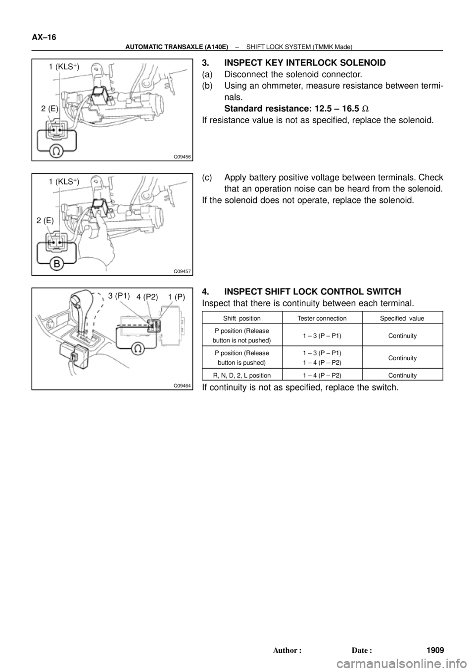
3. INSPECT KEY INTERLOCK SOLENOID
(a) Disconnect the solenoid connector.
(b) Using an ohmmeter, measure resistance between termi-
nals.
Standard resistance: 12.5 ± 16.5 W
If resistance value is not as specified, replace the solenoid.
(c) Apply battery positive voltage between terminals. Check
that an operation noise can be heard from the solenoid.
If the solenoid does not operate, replace the solenoid.
4. INSPECT SHIFT LOCK CONTROL SWITCH
Inspect that there is continuity between each terminal.
Shift positionTester connectionSpecified value
P position (Release
button is not pushed)1 ± 3 (P ± P1)Continuity
P position (Release
button is pushed)1 ± 3 (P ± P1)
1 ± 4 (P ± P2)Continuity
R, N, D, 2, L position1 ± 4 (P ± P2)Continuity
If continuity is not as specified, replace the switch.
Page 1777 of 4770
AUTOMATIC TRANSAXLE UNIT
AX±19
1912 Author�: Date�:
REMOVAL
1. REMOVE BATTERY
2. REMOVE AIR CLEANER ASSEMBLY
3. DISCONNECT THROTTLE")
AX03H±01
Q10055
Q00211
Q10056
Q10057
± AUTOMATIC TRANSAXLE (A140E)AUTOMATIC TRANSAXLE UNIT
AX±19
1912 Author�: Date�:
REMOVAL
1. REMOVE BATTERY
2. REMOVE AIR CLEANER ASSEMBLY
3. DISCONNECT THROTTLE CABLE
4. w/ CRUISE CONTROL:
REMOVE CRUISE CONTROL ACTUATOR
(a) Disconnect the connector.
(b) Remove the 3 bolts and disconnect cruise control actua-
tor with the bracket.
5. DISCONNECT OIL COOLER HOSE
6. DISCONNECT VEHICLE SPEED SENSOR CONNEC-
TOR
7. DISCONNECT PARK/NEUTRAL POSITION SWITCH
CONNECTOR
8. DISCONNECT SHIFT SOLENOID VALVE NO.1 AND
NO.2 CONNECTOR
9. DISCONNECT SHIFT SOLENOID VALVE SL CONNEC-
TOR
10. REMOVE 2 FRONT SIDE ENGINE MOUNTING BOLTS
Torque:
TMC made: 80 N´m (820 kgf´cm, 59 ft´lbf)
TMMK made:
Green color bolt: 66 N´m (670 kgf´cm, 48 ft´lbf)
Silver color bolt: 44 N´m (450 kgf´cm, 32 ft´lbf)
11. DISCONNECT 2 GROUND CABLES
12. REMOVE STARTER
(a) Disconnect the connector and remove the nut.
(b) Remove the 2 bolts, shift cable clamp and starter.
Torque: 39 N´m (400 kgf´cm, 29 ft´lbf)
13. REMOVE 3 TRANSAXLE±TO±ENGINE BOLTS
Torque: 66 N´m (670 kgf´cm, 48 ft´lbf)
Page 1801 of 4770
AUTOMATIC TRANSAXLEOPERATION ±
AX±5
3. HYDRAULIC CONTROL SYSTEM
The hydraulic control system is composed of the oil pump, the valve body, the solenoid valves, the accu-
mulators, the clutches and brakes as well as the fluid passages which connect all of these components.
Based on the hydraulic pressure created by the oil pump, the hydraulic control system governs the hy-
draulic pressure acting on the torque converter clutch, clutches and brakes in accordance with the ve-
hicle driving conditions.
There are three solenoid valves on the valve body.
The No.1 and No.2 solenoid vales are turned on and off by signals from the ECM to operate the shift
valves and change the gear shift position.
The SL solenoid valve is operated by signals from the ECM to engage or disengage the lock±up clutch
of the torque converter clutch.
The SLN solenoid valve is operated by signals from the ECM to control the engagement speed and
reduce gear shift shock.
AX01A±0B

SHIFT LOCK SYSTEM (")