Page 2891 of 4770
D00049
± DIAGNOSTICSAUTOMATIC TRANSAXLE (A541E)
DI±471
706 Author�: Date�:
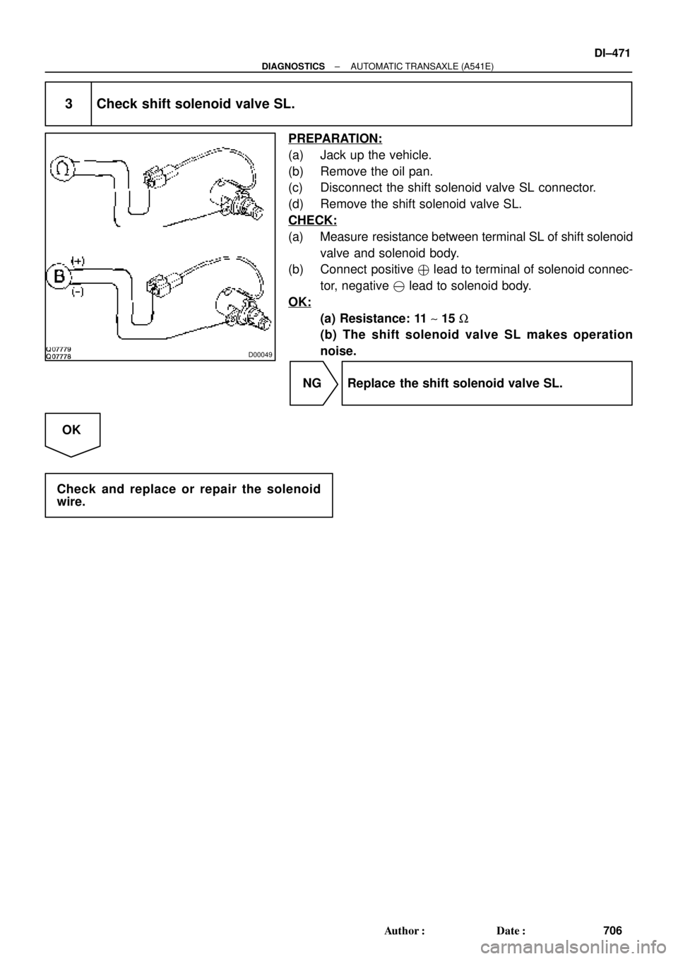
3 Check shift solenoid valve SL.
PREPARATION:
(a) Jack up the vehicle.
(b) Remove the oil pan.
(c) Disconnect the shift solenoid valve SL connector.
(d) Remove the shift solenoid valve SL.
CHECK:
(a) Measure resistance between terminal SL of shift solenoid
valve and solenoid body.
(b) Connect positive � lead to terminal of solenoid connec-
tor, negative � lead to solenoid body.
OK:
(a) Resistance: 11 ~ 15 W
(b) The shift solenoid valve SL makes operation
noise.
NG Replace the shift solenoid valve SL.
OK
Check and replace or repair the solenoid
wire.
Page 2893 of 4770

Q04869
NC2 Revolution Sensor
D01094
Direct Clutch
Speed Sensor 2V3
1
V3
G R
E99
E94ECM
NC2
+
NC2±4 ~ 6 V
*1: Except California, w/ Engine Immobilizer and / or TRAC
*2: California, w/ Engine Immobilizer and / or TRAC*2 *1
E1114
26 *2 *1
E11
± DIAGNOSTICSAUTOMATIC TRANSAXLE (A541E)
DI±473
708 Author�: Date�:
DTC P1705 NC2 Revolution Sensor Circuit Malfunction
(Direct Clutch Speed Sensor)
CIRCUIT DESCRIPTION
This sensor detects the rotation speed of the direct clutch drum.
By comparing the direct clutch speed signal and the vehicle
speed sensor signal, the ECM detects the shift timing of the
gears and appropriately controls the engine torque and hydrau-
lic pressure in response to various conditions, thus performing
smooth gear shifting.
DTC No.DTC Detecting ConditionTrouble Area
P1705
The ECM detects conditions (a), (b), (c), (d), (e) and (f) conti-
nuity for 4 sec or more.
(2 trip detection logic)
(a) Vehicle speed : 32 km/h (20 mph) or more
(b) 3rd or 4th gear
(c) NC2 < 300 rpm
(d) Park/neutral position switch: OFF
(e) Solenoid valves and vehicle speed sensor are normal
(f) L position: OFF
�Open or short in direct clutch speed sensor circuit
�Direct clutch speed sensor
�ECM
WIRING DIAGRAM
DI02P±02
Page 2896 of 4770

High
Accumulator Control Pressure
D00060
(*) Duty Ratio
The duty ratio is the ratio of the period of continuity in one cycle.
For example, if A is the period of continu")
AT5608
0
1
Electric Current (A)
High
Accumulator Control Pressure
D00060
(*) Duty Ratio
The duty ratio is the ratio of the period of continuity in one cycle.
For example, if A is the period of continuity in one cycle, and B is the period of non±continuity, then
D000621 msec./div.5 V/div.
GND Reference
Waveform between terminals SLN
+
and SLN± when engine is idling.Waveform between terminals SLN
+
and SLN± when during shift change.
1 msec./div.5 V/div.
GND DI±476
± DIAGNOSTICSAUTOMATIC TRANSAXLE (A541E)
711 Author�: Date�:
DTC P1765Linear Solenoid for Accumulator Pressure Control
Circuit Malfunction (Shift Solenoid Valve SLN)
CIRCUIT DESCRIPTION
The shift solenoid valve SLN controls the hydraulic pressure
acting on the accumulator control valve when gears are shifted
and performs smooth gear shifting.
The ECM determines optimum operating pressure according to
the signals from the throttle position sensor, vehicle speed sen-
sor and direct clutch speed sensor and controls the volume of
current flow to the solenoid valve.
The amount of current to the solenoid is controlled by the (*)
duty ratio of ECM output signals, causing a momentary change
to the hydraulic pressure acting on the clutches during gear
shifting.
When the duty ratio is high, the hydraulic pressure acting on the
clutches is low.
DTC No.DTC Detecting ConditionTrouble Area
P1765
After the engine is warmed up, the current flow to the shift
solenoid valve SLN for 1 sec or more under condition (a) or
(b):
(a) Engine speed: 500 rpm or more
(b) Park/neutral position switch: ON (P or N position)
�Open or short in shift solenoid valve SLN circuit
�Shift solenoid valve SLN
�ECM
DI02Q±02
Page 2897 of 4770
D01095
Shift Solenoid
Valve SLN 1
4
B±YW±L3
2
SLN
±
SLN+
ECM
*1: Except California, w/ Engine Immobilizer and / or TRAC
*2: California, w/ Engine Immobilizer and / or TRAC*2 *1
E11
E3E10
E9 E3*2 *1
1920
R
L
E11
D00050
2
1
21
± DIAGNOSTICSAUTOMATIC TRANSAXLE (A541E)
DI±477
712 Author�: Date�:
WIRING DIAGRAM
INSPECTION PROCEDURE
1 Check shift solenoid valve SLN.
PREPARATION:
Disconnect the shift solenoid valve SLN connector.
CHECK:
(a) Measure resistance between terminals 1 and 2 of sole-
noid connector.
(b) Connect positive � lead with an 8 ~10 W bulb to terminal
1 of solenoid connector and negative ��lead to terminal
2, then check the movement of the valve.
OK:
(a) Resistance: 5.1 ~ 5.5 W
(b)
When battery positive voltage is applied.Valve move in direction in illustration.
(on the left)
When battery positive voltage is cut off.Valve move in direction in illustration.
(on the right)
Page 2898 of 4770
D00051
(+)
(±)12
DI±478
± DIAGNOSTICSAUTOMATIC TRANSAXLE (A541E)
713 Author�: Date�:
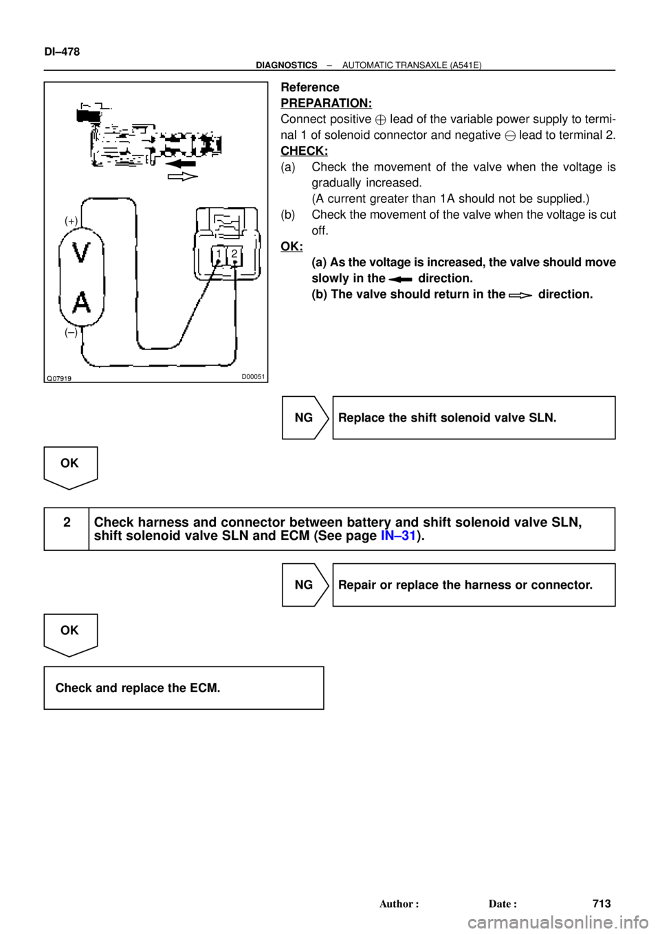
Reference
PREPARATION:
Connect positive � lead of the variable power supply to termi-
nal 1 of solenoid connector and negative ��lead to terminal 2.
CHECK:
(a) Check the movement of the valve when the voltage is
gradually increased.
(A current greater than 1A should not be supplied.)
(b) Check the movement of the valve when the voltage is cut
off.
OK:
(a) As the voltage is increased, the valve should move
slowly in the
direction.
(b) The valve should return in the
direction.
NG Replace the shift solenoid valve SLN.
OK
2 Check harness and connector between battery and shift solenoid valve SLN,
shift solenoid valve SLN and ECM (See page IN±31).
NG Repair or replace the harness or connector.
OK
Check and replace the ECM.
Page 3321 of 4770

*3: 5S±FE (w/o Immobiliser)
ECT No.2
SolenoidECT C15
6
C15 Y±B
L±B ECM
24 18 20
E8 E7 E7
*1 *2 *3 OD1
8216
E11
E9 E9
*1 *2 *")
I08432
S2OD 14Cruise Control ECU *1: 1MZ±FE
*2: 5S±FE (w/ Immobiliser)
*3: 5S±FE (w/o Immobiliser)
ECT No.2
SolenoidECT C15
6
C15 Y±B
L±B ECM
24 18 20
E8 E7 E7
*1 *2 *3 OD1
8216
E11
E9 E9
*1 *2 *3L±B L±B7
II2 J26
*1
J25*2
J/C
A
AA
± DIAGNOSTICSCRUISE CONTROL SYSTEM
DI±901
1136 Author�: Date�:
Electronically Controlled Transmission Communication Circuit
CIRCUIT DESCRIPTION
When driving uphill under the cruise control, in order to reduce shifting due to ON±OFF overdrive operation
and to provide smooth driving, when down shifting in the electronically controlled transmission occurs, a sig-
nal to prevent upshift until the end of the uphill slope is sent from the cruise control ECU to the electronically
controlled transmission.
Terminal ECT of the cruise control ECU detects the shift change signal (output to electronically controlled
transmission No. 2 solenoid) from the ECM.
If the vehicle speeds down, also when terminal ECT of the cruise control ECU receives down shifting signal,
it sends a signal from terminal OD to ECM to cut overdrive until the end of the uphill slope, and the gear shifts
are reduced and gear shift points in the electronically controlled transmission are changed.
WIRING DIAGRAM
DI08U±11
Page 4019 of 4770

SS±57
220 Author�: Date�:
TORQUE SPECIFICATION
Part tightenedN´mkgf´cmft´lbf
Front engine front mounting insulator x Front frame asse")
SS0BM±01
± SERVICE SPECIFICATIONSAUTOMATIC TRANSAXLE (A541E)
SS±57
220 Author�: Date�:
TORQUE SPECIFICATION
Part tightenedN´mkgf´cmft´lbf
Front engine front mounting insulator x Front frame assemblyTMC:
TMMK:
Green color bolt
Silver color bolt80
66
44820
670
45059
48
32
Rear engine mounting insulator x Front frame assembly8082059
LH transaxle mounting insulator x Transaxle6465047
Engine mounting absorber x Front frame assembly4849035
Transaxle x Engine 17 mm bolt6667048
Transaxle x Engine 12 mm bolt4849035
Torque converter clutch x Drive plate4142030
Valve body x Transaxle case1111 08
Oil strainer x Valve body1111 08
Oil pan x Transaxle case7.88069 in.´lbf
Oil pan drain plug4950036
Park/Neutral position switch x Transaxle case (bolt)5.45548 in.´lbf
Park/Neutral position switch (nut)6.97061 in.´lbf
B3 apply pipe retainer1111 08
Connector clamp1111 08
Manual valve body x Transaxle case1111 08
Detent spring x Manual valve body1111 08
Oil pipe bracket101007
Steering gear housing x Front suspension member1811,850134
Stabilizer bar bracket1919514
Vehicle speed sensor x Transaxle case4.95043 in.´lbf
Direct clutch speed sensor x Transaxle case1111 08
Transfer lubrication apply pipe retainer1111 08
Exhaust manifold bracket x Transaxle case Except California
California20
34200
35014
25
Exhaust manifold plate Except California
California20
34200
35014
25
Front frame x Body 19 mm1811,850134
Front frame x Body 14 mm3233024
Front frame x Body Nut3637027
Exhaust front pipe x Exhaust center pipe5657041
Exhaust manifold x Exhaust front pipe6263046
Exhaust front pipe support stay x Exhaust front pipe support bracket3333024
Exhaust pipe support x Front frame3333024
Starter x Torque converter clutch housing3940029
Transaxle control shaft lever x Park/neutral position switch1515011
Throttle cable adjusting nut1515011
Drive plate x Crankshaft8385061
Shift control cable x Transaxle control shaft lever1515011
Throttle cable retaining plate set bolt5.45548 in.´lbf
Shift solenoid valve No.1, No.2, SL, SLN x Valve body6.66758 in.´lbf