Page 1947 of 4770

1 (P)
4 (KLS+) 3 (IG)
6 (STP)
5 (E)
BBack Side
Front Side A
4 (P2)
5 (SLS±)
3 (P1)
2 (SLS+)
Q09460
5 (SLS±)
2 (SLS+)
Q09461
5 (SLS±)
2 (SLS+)
± AUTOMATIC TRANSAXLE (A541E)")
AX03W±01
Q09459
1 (ACC)
1 (P)
4 (KLS+) 3 (IG)
6 (STP)
5 (E)
BBack Side
Front Side A
4 (P2)
5 (SLS±)
3 (P1)
2 (SLS+)
Q09460
5 (SLS±)
2 (SLS+)
Q09461
5 (SLS±)
2 (SLS+)
± AUTOMATIC TRANSAXLE (A541E)SHIFT LOCK SYSTEM (TMMK Made)
AX±19
1939 Author�: Date�:
INSPECTION
1. INSPECT SHIFT LOCK CONTROL ECU
Using a voltmeter, measure voltage at each terminal.
HINT:
Do not disconnect the ECU connector.
TerminalMeasuring ConditionVoltage (V)
A, 1 ± A, 5 (ACC ± E)Ignition switch ACC10 ± 14
A, 3 ± A, 5 (IG ± E)Ignition switch ON10 ± 14
A, 6 ± A, 5 (STP ± E)Depressing brake pedal10 ± 14
A, 4 ± A, 5 (KLS+ ± E)
(1) Ignition switch ACC and P position
(2) Ignition switch ACC and except P position
(3) Ignition switch ACC and except P position (After approx. 1 second)0
7.5 ± 11
6 ± 9.5
B, 2 ± B, 5 (SLS+ ± SLS±)
(1) Ignition switch ON and P position
(2) Depress brake pedal
(3) Except P position0
8 ± 13.5
0
B, 3 ± B, 1 (P1 ± P)(1) Ignition switch ON, P position and depress brake pedal
(2) Shift except P position under conditions above0
9 ± 13.5
B, 4 ± B, 1 (P2 ± P)(1) Ignition switch ACC, P position
(2) Shift except P position under conditions above9 ± 13.5
0
2. INSPECT SHIFT LOCK SOLENOID
(a) Disconnect the solenoid connector.
(b) Using an ohmmeter, measure resistance between termi-
nals.
Standard resistance: 29 ± 35 W
If resistance value is not as specified, replace the solenoid.
(c) Apply battery positive voltage between terminals. Check
that operation.
If the solenoid does not operated, replace the solenoid noise
can be heard from the solenoid.
Page 1948 of 4770
Q09456
1 (KLS+)
2 (E)
Q09457
1 (KLS+)
2 (E)
(±) (+)
Q09464
3 (P1) 4 (P2) 1 (P) AX±20
± AUTOMATIC TRANSAXLE (A541E)SHIFT LOCK SYSTEM (TMMK Made)
1940 Author�: Date�:
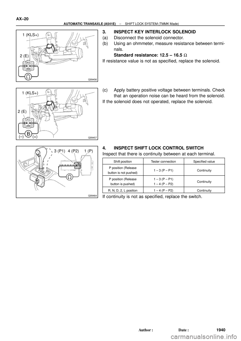
3. INSPECT KEY INTERLOCK SOLENOID
(a) Disconnect the solenoid connector.
(b) Using an ohmmeter, measure resistance between termi-
nals.
Standard resistance: 12.5 ± 16.5 W
If resistance value is not as specified, replace the solenoid.
(c) Apply battery positive voltage between terminals. Check
that an operation noise can be heard from the solenoid.
If the solenoid does not operated, replace the solenoid.
4. INSPECT SHIFT LOCK CONTROL SWITCH
Inspect that there is continuity between at each terminal.
Shift positionTester connectionSpecified value
P position (Release
button is not pushed)1 ± 3 (P ± P1)Continuity
P position (Release
button is pushed)1 ± 3 (P ± P1)
1 ± 4 (P ± P2)Continuity
R, N, D, 2, L position1 ± 4 (P ± P2)Continuity
If continuity is not as specified, replace the switch.
Page 1951 of 4770
AUTOMATIC TRANSAXLE UNIT
AX±23
1943 Author�: Date�:
REMOVAL
1. REMOVE BATTERY
2. REMOVE AIR CLEANER ASSEMBLY
3. REMOVE THROT")
AX03Y±01
Q00225
Q09982
Q10287
Q00075
Q10028
± AUTOMATIC TRANSAXLE (A541E)AUTOMATIC TRANSAXLE UNIT
AX±23
1943 Author�: Date�:
REMOVAL
1. REMOVE BATTERY
2. REMOVE AIR CLEANER ASSEMBLY
3. REMOVE THROTTLE CABLE FROM THROTTLE
BODY
Torque: 15 N´m (150 kgf´cm, 11 ft´lbf)
4. w/ Cruise Control:
REMOVE CRUISE CONTROL ACTUATOR
(a) Disconnect the connector.
(b) Remove the 3 bolts and disconnect cruise control actua-
tor with the bracket.
Torque: 13 N´m (130 kgf´cm, 9 ft´lbf)
5. DISCONNECT GROUND CABLE
6. DISCONNECT VEHICLE SPEED SENSOR CONNEC-
TOR
7. DISCONNECT DIRECT CLUTCH SPEED SENSOR
CONNECTOR
8. DISCONNECT PARK/NEUTRAL POSITION SWITCH
CONNECTOR
9. DISCONNECT SOLENOID CONNECTOR
10. DISCONNECT SHIFT CONTROL CABLE
(a) Remove the nut and disconnect the shift control cable
from the park/neutral position switch.
Torque: 15 N´m (150 kgf´cm, 11 ft´lbf)
(b) Remove the clip and disconnect the shift control cable.
11. REMOVE 2 ENGINE MOUNTING ABSORBER BOLTS
Torque: 48 N´m (490 kgf´cm, 35 ft´lbf)
Page 2435 of 4770

DI±15
250 Author�: Date�:
(b) TOYOTA Enhanced Signals.
TOYOTA hand±held tester displayMeasurement ItemNormal Condition*1
MISFIRE RPMEngine RPM for first misfire rangeMi")
± DIAGNOSTICSENGINE (5S±FE)
DI±15
250 Author�: Date�:
(b) TOYOTA Enhanced Signals.
TOYOTA hand±held tester displayMeasurement ItemNormal Condition*1
MISFIRE RPMEngine RPM for first misfire rangeMisfire 0: 0 rpm
MISFIRE LOADEngine load for first misfire rangeMisfire 0: 0 g/r
INJECTORFuel injection time for cylinder No.1Idling: 2.9 ~ 5.1 ms
IAC DUTY RATIOIntake Air Control Valve Duty Ratio
Opening ratio rotary solenoid type IAC valveIdling: 25 ~ 62 %
STARTER SIGStarter SignalCranking: ON
CTP SIGClosed Throttle Position SignalThrottle fully closed: ON
A/C SIGA/C Switch SignalA/C ON: ON
PNP SIGPark/Neutral Position Switch SignalP or N position: ON
ELECTCL LOAD SIGElectrical Load SignalDefogger S/W ON: ON
STOP LIGHT SWStop Light Switch SignalStop light switch ON: ON
PS OIL PRESS SWPower Steering Oil Pressure Switch SignalTurn steering wheel: ON
FC IDLFuel Cut Idle: Fuel cut when throttle valve fully
closed, during decelerationFuel cut operating: ON
FC TAUFuel Cut TAU: Fuel cut during very light loadFuel cut operating: ON
CYL#1, CYL#2, CYL#3, CYL#4Abnormal revolution variation for each cylinder0 %
IGNITIONTotal number of ignition for every 1,000 revolu-
tions0 ~ 2,000 rpm
EGR SYSTEMEGR system operating conditionIdling: OFF
FUEL PUMPFuel Pump SignalIdling: ON
A/C CUT SIGA/C Cut SignalA/C S/W OFF: ON
A/C MAG CLUTCHA/C Switch SignalA/C ON: ON
EVAP (PURGE) VSVEVAP VSV SignalVSV operating: Avove 30 %
VAPOR PRESS VSVVapor Pressure VSV SignalVSV operating: ON
TOTAL FT B1Total Fuel Trim Bank 1: Average value for fuel
trim system of bank 1Idling: 0.8 ~ 1.2 V
O2 LR B1, S1 *2
Heated Oxygen Sensor Lean Rich Bank 1 Sen-
sor 1: Response time for oxygen sensor output to
switch from lean to rich
Idling after warming up: 0 ~ 1,000 msec.
O2 RL B1, S1 *2
Heated Oxygen Sensor Rich Lean Bank 1 Sen-
sor 1: Response time for oxygen sensor output to
switch from rich to lean
Idling after warming up: 0 ~ 1,000 msec.
*1: If no conditions are specifically stated for ºldlingº, it means the shift lever is at N or P position, the A/C
switch is OFF and all accessory switches are OFF.
*2: Except California Specification vehicles.
Page 2629 of 4770

DI±209
444 Author�: Date�:
(b) TOYOTA Enhanced Signals.
TOYOTA hand±held tester displayMeasurement ItemNormal Condition*
MISFIRE RPMEngine RPM for first misfire rangeM")
± DIAGNOSTICSENGINE (1MZ±FE)
DI±209
444 Author�: Date�:
(b) TOYOTA Enhanced Signals.
TOYOTA hand±held tester displayMeasurement ItemNormal Condition*
MISFIRE RPMEngine RPM for first misfire rangeMisfire 0: 0 rpm
MISFIRE LOADEngine load for first misfire rangeMisfire 0: 0 g/r
INJECTORFuel injection time for cylinder No.1Idling: 1.6 ~ 2.9 ms
IAC DUTY RATIOIntake Air Control Valve Duty Ratio
Opening ratio rotary solenoid type IAC valveIdling: 27 ~ 47 %
STARTER SIGStarter SignalCranking: ON
CTP SIGClosed Throttle Position SignalThrottle Fully Closed: ON
A/C SIGA/C Switch SignalA/C ON: ON
PNP SWPark/Neutral Position Switch SignalP or N position: ON
ELCTRCL LOAD SIGElectrical Load SignalDefogger switch ON: ON
STOP LIGHT SWStop Light Switch SignalStop light switch ON: ON
PS OIL PRESS SWPower Steering Oil Pressure Switch SignalTurn steering wheel: ON
FC IDLFuel Cut Idle: Fuel cut when throttle valve fully
closed, during decelerationFuel cut operating: ON
FC TAUFuel Cut TAU: Fuel cut during very light loadFuel cut operating: ON
CYL#1 ~ CYL#6Abnormal revolution variation for each cylinder0%
IGNITIONTotal number of ignition for every 1,000 revolu-
tions0 ~ 3,000
EGRT GASEGR Gas Temperature Sensor Value
EGR not operating:
Temperature between intake air temp. and
engine coolant temp.
INTAKE CTRL VSVIntake Air Control Valve VSV SignalVSV operating: ON
EGR SYSTEMEGR system operating conditionIdling: OFF
A/C CUT SIGA/C Cut SignalA/C S/W OFF: ON
FUEL PUMPFuel Pump SignalIdling: ON
EVAP (PURGE) VSVEVAP VSV SignalVSV operating: Above 30%
VAPOR PRESS VSVVapor Pressure VSV SignalVSV operating: ON (TANK)
*: If no conditions are specifically stated for ºldlingº, it means the shift lever is at N or P position, the A/C switch
is OFF and all accessory switches are OFF.
Page 2820 of 4770
Q00200
DI±400
± DIAGNOSTICSAUTOMATIC TRANSAXLE (A140E)
635 Author�: Date�:
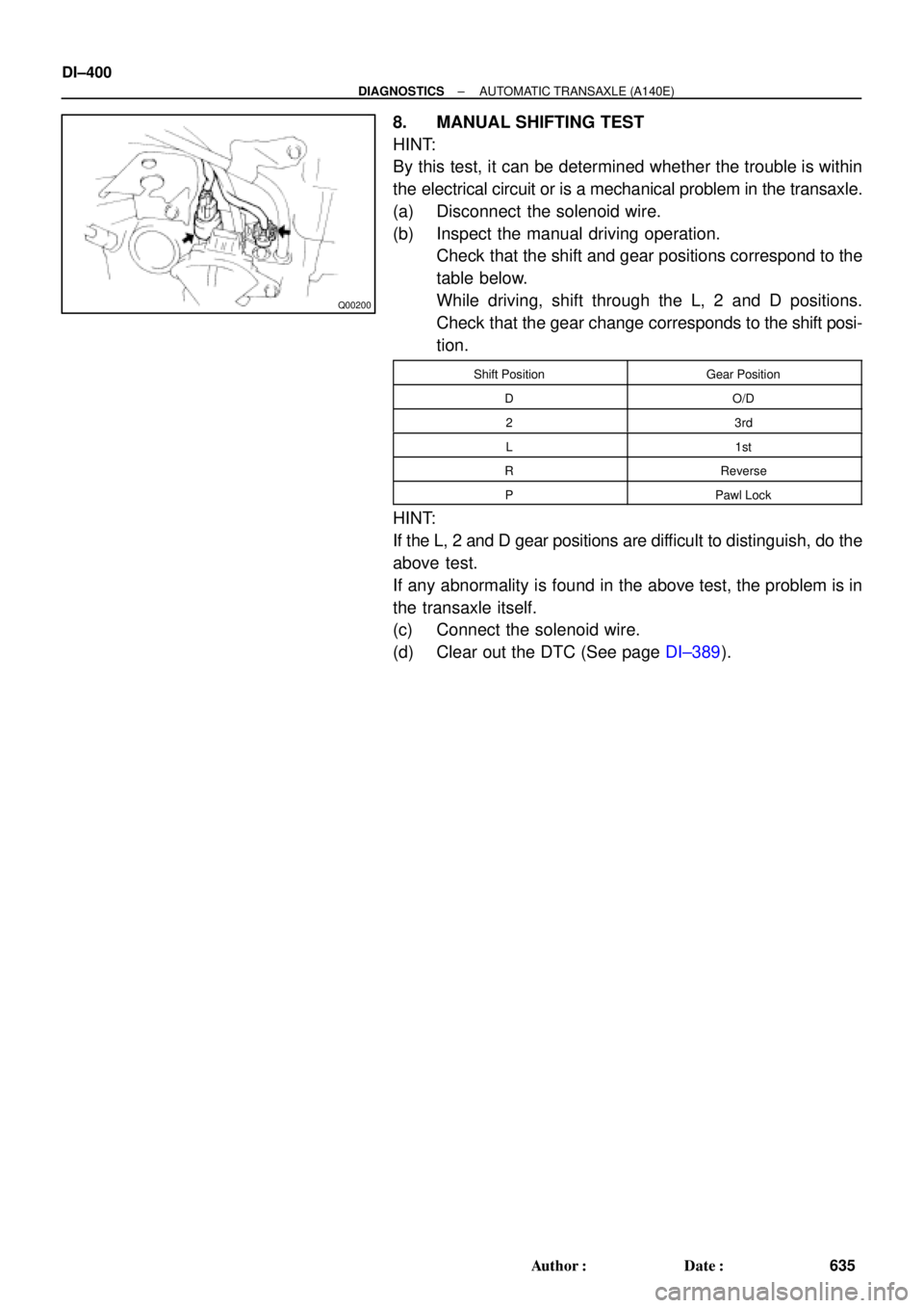
8. MANUAL SHIFTING TEST
HINT:
By this test, it can be determined whether the trouble is within
the electrical circuit or is a mechanical problem in the transaxle.
(a) Disconnect the solenoid wire.
(b) Inspect the manual driving operation.
Check that the shift and gear positions correspond to the
table below.
While driving, shift through the L, 2 and D positions.
Check that the gear change corresponds to the shift posi-
tion.
Shift PositionGear Position
DO/D
23rd
L1st
RReverse
PPawl Lock
HINT:
If the L, 2 and D gear positions are difficult to distinguish, do the
above test.
If any abnormality is found in the above test, the problem is in
the transaxle itself.
(c) Connect the solenoid wire.
(d) Clear out the DTC (See page DI±389).
Page 2821 of 4770

DI±401
636 Author�: Date�:
DIAGNOSTIC TROUBLE CODE CHART
If a DTC is displayed during the DTC check, check the circuit listed for that code in the")
DI02X±02
± DIAGNOSTICSAUTOMATIC TRANSAXLE (A140E)
DI±401
636 Author�: Date�:
DIAGNOSTIC TROUBLE CODE CHART
If a DTC is displayed during the DTC check, check the circuit listed for that code in the table below and pro-
ceed to the page given.
* : �...MIL light up
DTC No.
(See Page)Detection ItemTrouble AreaMIL *Memory
P0500
(DI±408)Vehicle Speed Sensor Malfunc-
tion
(No.1 Vehicle Speed Sensor)
�Open or short in No.1 vehicle speed sensor circuit
�No.1 vehicle speed sensor
�Combination meter
�ECM
�Automatic transaxle (clutch, brake or gear etc.)
��
P0750
(DI±411)Shift Solenoid A Malfunction
(Shift Solenoid Valve No.1)�Shift solenoid valve No.1 is stuck open or closed
�Valve body is blocked up or stuck
�Automatic transaxle (clutch, brake or gear etc.)
��
P0753
(DI±413)Shift Solenoid A Electrical Mal-
function
(Shift Solenoid Valve No.1)�Open or short in shift solenoid valve No.1 circuit
�Shift solenoid valve No.1
�ECM
��
P0755
(DI±411)Shift Solenoid B Malfunction
(Shift Solenoid Valve No.2)�Shift solenoid valve No.2 is stuck open or closed
�Valve body is blocked up or stuck
�Automatic transaxle (clutch, brake or gear etc.)
��
P0758
(DI±413)Shift Solenoid B Electrical Mal-
function
(Shift Solenoid Valve No.2)�Open or short in shift solenoid valve No.2 circuit
�Shift solenoid valve No.2
�ECM
��
P0770
(DI±417)Shift Solenoid E Malfunction
(Shift Solenoid Valve SL)
�Shift solenoid valve SL is stuck open or closed
�Valve body is blocked up or stuck
�Lock±up clutch
�Automatic transaxle (clutch, brake or gear etc.)
��
P0773
(DI±419)Shift Solenoid E Electrical Mal-
function
(Shift Solenoid Valve SL)�Open or short in shift solenoid valve SL circuit
�Shift solenoid valve SL
�ECM
��
P1520
(DI±170)Stop Light Switch Signal Mal-
function�Open or short in stop light switch circuit
�Stop light switch
�ECM
��
P1780
(DI±424)Park/Neutral Position Switch
Malfunction�Short in park/neutral position switch circuit
�Park/neutral position switch
�ECM
��
Page 2822 of 4770
DI02Y±02
D00938
Shift Solenoid Valve SLVehicle Speed SensorECMO/D Main SwitchO/D OFF Indicator Light
DLC3
Stop Light Switch
Shift Solenoid Valve No.2
Shift Solenoid Valve No.1 Park/Neutral Position Switch
DI±402
± DIAGNOSTICSAUTOMATIC TRANSAXLE (A140E)
637 Author�: Date�:
PARTS LOCATION