Page 2823 of 4770

DI1IZ±01
FI6526
1 2 3 4
5 6 7
8 9 10
12 13
14 15 17
18 19
20 21 22 1 2 3 4 5 6
7 8
9
10 11 12 1 2
3
4 5 6 7
8
9 1011
11 12 13
1514
16 16 1 2 3 4
5 6 7 8 9 10
12 13
14
15 17 18 19
20 21 22 11
16 23 24
25 26
ECM TerminalsE9 E8
E7E10
± DIAGNOSTICSAUTOMATIC TRANSAXLE (A140E)
DI±403
638 Author�: Date�:
TERMINALS OF ECM
w/ Engine Immobiliser System
Symbols (Terminals No.)Wiring ColorConditionSTD Voltage (V)
IG ON9 ~ 14
S1 e E1 (E9±8 e E9±24)V e BR1st or 2nd gear9 ~ 14S1 e E1 (E9 8 e E9 24)V e BR
3rd or O/D gearBelow 1
IG ONBelow 1
S2 e E1 (E9±21 e E9±24)L±B e BR1st or 2nd gear9 ~ 14S2 e E1 (E9 21 e E9 24)LB e BR
3rd or O/D gearBelow 1
SLE1 (E9 20E9 24)PBRIG ONBelow 1SL e E1 (E9±20 e E9±24)P e BRVehicle driving under lock±up position9 ~ 14
OD1 e E1 (E7±18 e E9±24)Y±B e BRIG ON9 ~ 14
OD2E1 (E7 5E9 24)GOBRO/D main switch ON9 ~ 14OD2 e E1 (E7±5 e E9±24)G±O e BRO/D main switch OFFBelow 1
LE1 (E7 15E9 24)YBRIG ON and Shift lever L position9 ~ 14L e E1 (E7±15 e E9±24)Y e BRIG ON and Shift lever other than L positionBelow 1
2E1 (E7 16E9 24)*1L±W e BRIG ON and Shift lever 2 position9 ~ 142 e E1 (E7±16 e E9±24)LW e BR
*2O e BRIG ON and Shift lever other than 2 positionBelow 1
RE1 (E7 17 E9 24)RBBRIG ON and Shift lever R position9 ~ 14R e E1 (E7±17 ± E9±24)R±B e BRIG ON and Shift lever other than R positionBelow 1
NSWE1 (E7 22E9 24)BWBRIG ON and Shift lever P or N position9 ~ 14NSW e E1 (E7±22 e E9±24)B±W e BRIG ON and Shift lever other than P or N positionBelow 1
*1: TMC made
*
2: TMMK made
Page 2824 of 4770

639 Author�: Date�:
w/o Engine Immobiliser System
Symbols (Terminals No.)Wiring ColorConditionSTD Voltage (V)
IG ON9 ~ 14
S1 e")
ECM Terminals
E9 E8
E7 DI±404
± DIAGNOSTICSAUTOMATIC TRANSAXLE (A140E)
639 Author�: Date�:
w/o Engine Immobiliser System
Symbols (Terminals No.)Wiring ColorConditionSTD Voltage (V)
IG ON9 ~ 14
S1 e E1 (E9±7 e E9±14)
V e BR1st or 2nd gear9 ~ 14S1 e E1 (E9 7 e E9 14)
V e BR
3rd or O/D gearBelow 1
IG ONBelow 1
S2 e E1 (E9±6 e E9±14)L±B e BR1st or 2nd gear9 ~ 14S2 e E1 (E9 6 e E9 14)LB e BR
3rd or O/D gearBelow 1
SLE1 (E9 1E9 14)PBRIG ONBelow 1SL e E1 (E9±1 e E9±14)P e BRVehicle driving under lock±up position9 ~ 14
OD1 e E1 (E7±20 e E9±14)Y±B e BRIG ON9 ~ 14
OD2E1 (E7 7E9 14)GOBRO/D main switch ON9 ~ 14OD2 e E1 (E7±7 e E9±14)G±O e BRO/D main switch OFFBelow 1
LE1 (E7 19E9 14)YBRIG ON and Shift lever L position9 ~ 14L e E1 (E7±19 e E9±14)Y e BRIG ON and Shift lever other than L positionBelow 1
2E1 (E7 18E9 14)*1L±W e BRIG ON and Shift lever 2 position9 ~ 142 e E1 (E7±18 e E9±14)LW e BR
*2O e BRIG ON and Shift lever other than 2 positionBelow 1
RE1 (E7 17 E9 14)RBBRIG ON and Shift lever R position9 ~ 14R e E1 (E7±17 ± E9±14)R±B e BRIG ON and Shift lever other than R positionBelow 1
NSWE1 (E7 22E9 14)BWBRIG ON and Shift lever P or N position9 ~ 14NSW e E1 (E7±22 e E9±14)B±W e BRIG ON and Shift lever other than P or N positionBelow 1
*1: TMC made
*
2: TMMK made
Page 2825 of 4770

DI±405
640 Author�: Date�:
PROBLEM SYMPTOMS TABLE
If a normal code is displayed during the DTC check but the trouble still occurs, check the circui")
DI030±02
± DIAGNOSTICSAUTOMATIC TRANSAXLE (A140E)
DI±405
640 Author�: Date�:
PROBLEM SYMPTOMS TABLE
If a normal code is displayed during the DTC check but the trouble still occurs, check the circuits for each
symptom in the order given in the charts on the following pages and proceed to the page given for trouble-
shooting.
The Matrix Chart is divided into 3 chapters.
Chapter 1: Electronic Circuit Matrix Chart
Chapter 2: On±vehicle Repair Matrix Chart
Chapter 3: Off±vehicle repair Matrix Chart
�If the instruction ºProceed to next circuit inspection shown on matrix chartº is given in the flow
chart for each circuit, proceed to the circuit with the next highest number in the table to continue
the check.
�If the trouble still occurs even though there are no abnormalities in any of the other circuits, then
check and replace the ECM.
1. Chapter 1: Electronic Circuit Matrix Chart
SymptomSuspect AreaSee page
No up±shift
(A particular gear, from 1st to 3rd gear, is not up±shifted)1. ECMIN±31
No up±shift (3rd " O/D)
1. O/D main switch & O/D OFF indicator light circuit
2. O/D cancel signal circuit
3. ECMDI±431
DI±428
IN±31
No down±shift (O/D " 3rd)1. ECMIN±31
No down±shift
(A particular gear, from 3rd to 1st gear, is not down±shifted)1. ECMIN±31
No lock±up or No lock±up off1. Stop light switch circuit
2. ECMDI±423
IN±31
Shift point too high or too low1. ECMIN±31
Up±shift to O/D from 3rd while O/D main switch is OFF1. O/D main switch & O/D OFF indicator light circuit
2. ECMDI±431
IN±31
Up±shift to O/D from 3rd while engine is cold1. ECMIN±31
Poor acceleration1. ECMIN±31
No kick±down1. ECMIN±31
Engine stalls when starting off or stopping1. ECMIN±31
Page 2826 of 4770

641 Author�: Date�:
2. Chapter 2: On±Vehicle Repair
(�: A140E AUTOMATIC TRANSAXLE Repair Manual Pub. No. RM385U)
SymptomSuspect AreaSee page
Vehicle")
DI±406
± DIAGNOSTICSAUTOMATIC TRANSAXLE (A140E)
641 Author�: Date�:
2. Chapter 2: On±Vehicle Repair
(�: A140E AUTOMATIC TRANSAXLE Repair Manual Pub. No. RM385U)
SymptomSuspect AreaSee page
Vehicle does not move in any forward positions and reverse posi-
tion
1. Manual valve
2. Throttle valve
3. Primary regulator valve
4. Off±vehicle repair matrix chart�
�
�
±
Vehicle does not move in R position1. Off±vehicle repair matrix chart±
No up±shift (1st " 2nd)1. 1±2 shift valve
2. Off±vehicle repair matrix chart�
±
No up±shift (2nd " 3rd)1. 2±3 shift valve
2. Off±vehicle repair matrix chart�
±
No up±shift (3rd " O/D)1. 3±4 shift valve
2. Off±vehicle repair matrix chart�
±
No down±shift (O/D " 3rd)1. 3±4 shift valve�
No down±shift (3rd " 2nd)1. 2±3 shift valve�
No down±shift (2nd " 1st)1. 1±2 shift valve�
No lock±up or No lock±up off1. Lock±up relay valve
2. Off±vehicle repair matrix chart�
±
Harsh engagement (N " D)1. C1 accumulator
2. Off±vehicle repair matrix chart�
±
Harsh engagement (N " R)1. C2 accumulator
2. Off±vehicle repair matrix chart�
±
Harsh engagement (N " L)1. Low coast modulator valve�
Harsh engagement (Lock±up)1. Lock±up relay valve
2. Off±vehicle repair matrix chart�
±
Harsh engagement (1st " 2nd " 3rd " O/D)
1. Throttle modulator valve
2. Cut back valve
3. Throttle valve�
�
�
Harsh engagement (2nd " 3rd)1. C2 accumulator�
Harsh engagement (3rd " O/D)1. B0 accumulator�
Harsh engagement (O/D " 3rd)1. C0 accumulator
2. B
0 accumulator
�
�
Slip or shudder (Forward and reverse)
1. Throttle valve
2. Oil strainer
3. Off±vehicle repair matrix chart�
�
±
No engine braking (1st: L position)1. Low coast modulator valve
2. Off±vehicle repair matrix chart�
±
No engine braking (2nd: 2 position)1. 2nd coast modulator valve
2. Off±vehicle repair matrix chart�
±
No kick±down
1. 1±2 shift valve
2. 2±3 shift valve
3. 3±4 shift valve�
�
�
Page 2827 of 4770

DI±407
642 Author�: Date�:
3. Chapter 3: Off±Vehicle Repair
(�: A140E AUTOMATIC TRANSAXLE Repair Manual Pub. No. RM385U)
SymptomSuspect AreaSee page
Vehicl")
± DIAGNOSTICSAUTOMATIC TRANSAXLE (A140E)
DI±407
642 Author�: Date�:
3. Chapter 3: Off±Vehicle Repair
(�: A140E AUTOMATIC TRANSAXLE Repair Manual Pub. No. RM385U)
SymptomSuspect AreaSee page
Vehicle does not move in any forward positions and reverse posi-
tion
1. Front and rear planetary gear
2. O/D planetary gear
3. O/D one±way clutch (F
0)
4. O/D direct clutch (C
0)
5. O/D brake (B
0)
6. Forward clutch (C
1)
�
�
�
�
�
�
Vehicle does not move in R position
1. Front and rear planetary gear unit
2. Direct clutch (C
2)
3. O/D direct clutch (C
0)
4. 1st & reverse brake (B
3)
�
�
�
�
No up±shift (1st " 2nd)1. No. 1 one±way clutch (F1)
2. 2nd brake (B
2)
�
�
No up±shift (2nd " 3rd)1. Direct clutch (C2)�
No up±shift (3rd " O/D)1. O/D brake (B0)�
No lock±up or No lock±up off1. Torque converter clutchAX±26
Harsh engagement (N " D)
1. Forward clutch (C1)
2. O/D one±way clutch (F
0)
3. No. 2 one±way clutch (F
2)
�
�
�
Harsh engagement (N " R)1. Direct clutch (C2)
2. 1st & reverse brake (B
3)
�
�
Harsh engagement (Lock±up)1. Torque converter clutchAX±26
Slip or shudder (Forward position: After warm±up)
1. Torque converter clutch
2. O/D direct clutch (C
0)
3. Forward clutch (C
1)
4. O/D one±way clutch (F
0)
AX±26
�
�
�
Slip or shudder (R position)
1. Direct clutch (C2)
2. 1st & reverse brake (B
3)
3. O/D direct clutch (C
0)
�
�
�
Slip or shudder (1st)1. No. 2 one±way clutch (F2)�
Slip or shudder (2nd)1. No. 1 one±way clutch (F1)
2. 2nd brake (B
2)
�
�
Slip or shudder (3rd)1. Direct clutch (C2)�
Slip or shudder (O/D)1. O/D brake (B0)�
No engine braking (1st ~ 3rd: D position)1. 2nd brake (B2)�
No engine braking (1st: L position)1. 1st & reverse brake (B3)�
No engine braking (2nd: 2 position)1. 2nd coast brake (B1)�
Poor acceleration (All positions)1. Torque converter clutch
2. O/D planetary gearAX±26
�
Poor acceleration (O/D)1. O/D direct clutch (C0)
2. O/D planetary gear�
�
Large shift shock or engine stalls when starting off or stopping1. Torque converter clutchAX±26
Page 2829 of 4770
 w/ Engine Immobiliser System
w/o Engine Immobiliser System(+)
(±)
(+)
AT7809
4.5 ~ 5.5 V
0
Turn the wheel
± DIAGNOSTICSAUTOMATIC TRANSAXLE (A140E)
DI±409
644 Author�: D")
A03021D02238
SPD
SPD
ON
(±) w/ Engine Immobiliser System
w/o Engine Immobiliser System(+)
(±)
(+)
AT7809
4.5 ~ 5.5 V
0
Turn the wheel
± DIAGNOSTICSAUTOMATIC TRANSAXLE (A140E)
DI±409
644 Author�: Date�:
INSPECTION PROCEDURE
1 Check operation of speedometer.
CHECK:
Drive the vehicle and check if the operation of the speedmeter in the combination meter is normal.
HINT:
The vehicle speed sensor is operating normally if the speedometer display is normal.
NG Check speedometer circuit. See combination
meter troubleshooting (See page BE±47).
OK
2 Check voltage between terminal SPD of ECM connector and body ground.
PREPARATION:
(a) Remove glove compartment (See page BO±75).
(b) Shift the shift lever to neutral.
(c) Jack up one of the front wheels.
(d) Turn ignition switch ON.
CHECK:
Measure voltage between terminal SPD of ECM connector and
body ground when the wheel is turned slowly.
OK:
Voltage is generated intermittently.
NG Check and repair harness and connector
between combination meter and ECM
(See page IN±31).
OK
Page 2834 of 4770
D01807
W3
E4 Transaxle
Shift Solenoid
Valve No.1
Shift Solenoid
Valve No.2
*2: w/o Engine
Immobiliser SystemE4 B1V7
21
*2
E9S1
*1: w/ Engine
Immobiliser System
A L ± B
*18
6
*2*1
E9
E9E9 L ± B J25
Junction
Connector
AAS2B+
B+
Cruise Control ECUECM
D00102 Q10102D00990
w/ Engine Immobiliser System
w/o Engine Immobiliser SystemS2
S1
S1
S2
DI±414
± DIAGNOSTICSAUTOMATIC TRANSAXLE (A140E)
649 Author�: Date�:
WIRING DIAGRAM
INSPECTION PROCEDURE
1 Measure resistance between terminal S1 or S2 of ECM and body ground.
PREPARATION:
Disconnect the connector from ECM.
CHECK:
Measure resistance between terminal S1 or S2 of ECM and
body ground.
OK:
Resistance: 11 ~ 15 W
OK Check and replace the ECM.
NG
Page 2835 of 4770
D00104 D00958D00991
w/ Engine Immobiliser System
w/o Engine Immobiliser SystemS2S1
S1S2
S1
S2 S1
S2
± DIAGNOSTICSAUTOMATIC TRANSAXLE (A140E)
DI±415
650 Author�: Date�:
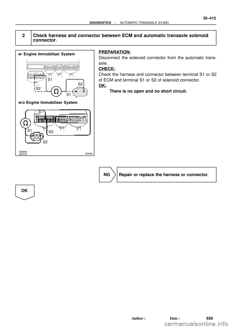
2 Check harness and connector between ECM and automatic transaxle solenoid
connector.
PREPARATION:
Disconnect the solenoid connector from the automatic trans-
axle.
CHECK:
Check the harness and connector between terminal S1 or S2
of ECM and terminal S1 or S2 of solenoid connector.
OK:
There is no open and no short circuit.
NG Repair or replace the harness or connector.
OK