Page 4297 of 4770

Z15498
Oil
PS Gear
Closed
SSTPS Vane
Pump Reservoir
Z15499
Oil
PS Gear
SSTPS Vane
Pump Reservoir
Open
Z15500
Oil
PS Gear
SSTPS Vane
Pump Reservoir
Lock Position
± STEERINGPOWER STEERING FLUID
SR±7
2102 Author�: Date�:
(f) With the engine idling, close the valve of the SST and ob-
serve the reading on the SST.
Minimum fluid pressure:
7,845 kPa (80 kgf´cm
2, 1,138 psi)
NOTICE:
�Do not keep the valve closed for more than 10 se-
conds.
�Do not let the fluid temperature become too high.
(g) With the engine idling, open the valve fully.
(h) Measure the fluid pressure at engine speeds of 1,000 rpm
and 3,000 rpm.
Difference fluid pressure:
490 kPa (5 kgf´cm
2, 71 psi) or less
NOTICE:
Do not turn the steering wheel.
(i) With the engine idling and valve fully opened, turn the
steering wheel to full lock.
Minimum fluid pressure:
7,845 kPa (80 kgf´cm
2, 1,138 psi)
NOTICE:
�Do not maintain lock position for more than 10 se-
conds.
�Do not let the fluid temperature become too high.
(j) Disconnect the SST.
(k) Connect the pressure feed tube.
(See page SR±28)
(l) Bleed the power steering system.
(See page SR±4)
Page 4308 of 4770
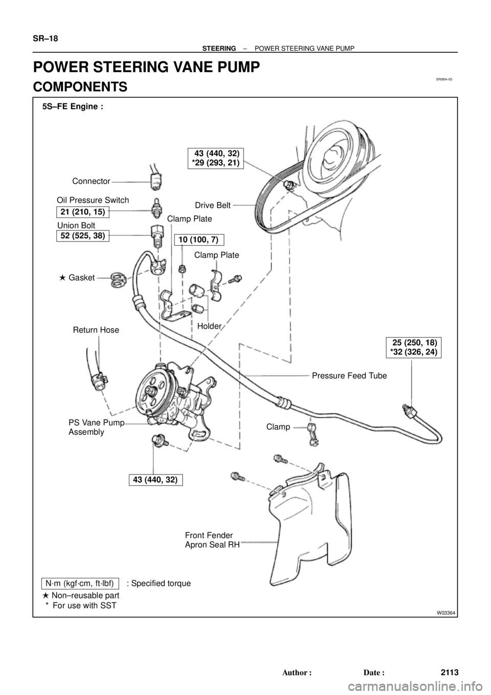
SR06N±03
W03364
Pressure Feed Tube Connector
Oil Pressure Switch
Drive Belt
Clamp Plate
Clamp Plate
Holder
Clamp
Front Fender
Apron Seal RH PS Vane Pump
AssemblyReturn Hose � Gasket Union Bolt 5S±FE Engine :
21 (210, 15)
43 (440, 32)
*29 (293, 21)
10 (100, 7)
25 (250, 18)
*32 (326, 24)
43 (440, 32)
52 (525, 38)
N´m (kgf´cm, ft´lbf) : Specified torque
� Non±reusable part
For use with SST * SR±18
± STEERINGPOWER STEERING VANE PUMP
2113 Author�: Date�:
POWER STEERING VANE PUMP
COMPONENTS
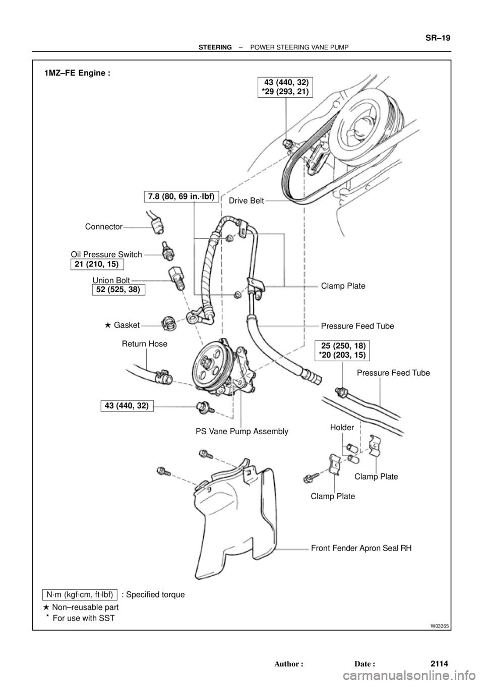
Page 4309 of 4770
W03365
Drive Belt
Clamp Plate
Pressure Feed Tube
Pressure Feed Tube
Clamp Plate
Clamp Plate
Front Fender Apron Seal RH
N´m (kgf´cm, ft´lbf)
� Non±reusable part
For use with SST: Specified torquePS Vane Pump Assembly Return Hose � Gasket Union Bolt Connector
Oil Pressure Switch
43 (440, 32)
52 (525, 38)
21 (210, 15)
7.8 (80, 69 in.´lbf)
25 (250, 18)
*20 (203, 15)
43 (440, 32)
*29 (293, 21) 1MZ±FE Engine :
Holder
*
± STEERINGPOWER STEERING VANE PUMP
SR±19
2114 Author�: Date�:
Page 4310 of 4770
W03349
Pressure Port Union
� Oil Ring
Flow Control Valve
Suction Port Union
Spring
� O±Ring
Front Housing� Gasket Rear Housing
Rear Bracket
Rear Housing
� O±Ring
Rear Bracket
Wave Washer
�
Cam Ring � Straight Pin
Vane Plate Rotor
Side Plate Vane Pump
x10
� O±Ring
� Snap Ring
N´m (kgf´cm, ft´lbf)
Non±reusable part
Power steering fluid: Specified torque Vane Pump Shaft
Vane Pump PulleyFront Bracket Front Bracket
�
5S±FE Engine :
TOYOTA KOUKI Made :24 (240, 17)
43 (440, 32)
24 (240, 17)
83 (850, 62)
13 (130, 9)
5S±FE Engine :5S±FE Engine :
1MZ±FE Engine :1MZ±FE Engine :
43 (440, 32)
43 (440, 32) SR±20
± STEERINGPOWER STEERING VANE PUMP
2115 Author�: Date�:
Page 4311 of 4770

SR06O±01
W04220
5S±FE Engine :
1MZ±FE Engine :
Pressure
Feed TubeSST SST
W03360
Example 5S±FE Engine :
A
B
± STEERINGPOWER STEERING VANE PUMP
SR±21
2116 Author�: Date�:
REMOVAL
1. REMOVE FRONT FENDER APRON SEAL RH
Remove the 2 bolts.
2. DISCONNECT RETURN HOSE
NOTICE:
Take care not to spill fluid on the drive belt.
3. DISCONNECT PRESSURE FEED TUBE
(a) 5S±FE Engine:
Remove the clamp plate set bolt and nut.
(b) 5S±FE Engine:
Remove the 2 clamp plates and 2 holders from the tube.
(c) 5S±FE Engine:
Remove the clamp from the tube.
(d) 1MZ±FE Engine:
Remove the 2 clamp plate set nuts.
(e) 1MZ±FE Engine:
Remove the bolt.
(f) 1MZ±FE Engine:
Remove the 2 clamp plates and 2 holders from the tube.
(g) 5S±FE and 1MZ±FE Engines:
Using SST, disconnect the tube.
SST 09631±22020
4. REMOVE DRIVE BELT
Loosen the 2 (A and B) bolts.
5. REMOVE PS VANE PUMP ASSEMBLY WITH PRES-
SURE FEED TUBE
(a) Disconnect the connector from the oil pressure switch.
(b) Loosen bolt A sufficiently so that pump assembly can be
removed.
HINT:
Bolt A cannot be removed.
6. REMOVE PRESSURE FEED TUBE
(a) Remove the oil pressure switch from the union bolt.
NOTICE:
Be careful not to drop the switch.
If the switch is dropped or strongly damaged, replace it with a
new one.
(b) Remove the union bolt and gasket.
Page 4312 of 4770

SR06P±01
W03338
Example 5S±FE Engine :
W03339
Example 5S±FE Engine :
SST SR±22
± STEERINGPOWER STEERING VANE PUMP
2117 Author�: Date�:
DISASSEMBLY
NOTICE:
When using a vise, do not overtighten it.
1. MEASURE PS VANE PUMP ROTATING TORQUE
(a) Check that the pump rotates smoothly without abnormal
noise.
(b) Using a torque wrench, check the pump rotating torque.
5S±FE and 1MZ±FE Engines:
Rotating torque:
0.3 N´m (2.8 kgf´cm, 2.4 in.´lbf) or less
2. REMOVE VANE PUMP PULLEY
Using SST, to stop the pulley rotating, remove the nut.
SST 09960±10010 (09962±01000, 09963±01000)
3. REMOVE FRONT AND REAR BRACKETS
Remove the 3 bolts and 2 nuts.
4. REMOVE SUCTION PORT UNION
(a) Remove the bolt.
(b) Remove the O±ring from the union.
5. REMOVE PRESSURE PORT UNION, FLOW CONTROL
VALVE AND SPRING
Remove the O±ring from the union.
6. REMOVE REAR HOUSING
(a) Remove the 4 bolts.
(b) Remove the 2 O±rings from the housing.
7. REMOVE WAVE WASHER
8. REMOVE SIDE PLATE
9. REMOVE GASKET
10. REMOVE CAM RING, 10 VANE PLATES AND VANE
PUMP ROTOR
Using a screwdriver, remove the snap ring from the vane pump
shaft.
NOTICE:
Take care not to drop the plate.
11. REMOVE VANE PUMP SHAFT
12. REMOVE STRAIGHT PINS
Remove the 2 pins from the front housing.
Page 4313 of 4770

SR06Q±01
R15196
Caliper Gauge
Micrometer
Vane Pump Shaft
Bushing
Front Housing
N00372
Thickness
Height
Length
R10282
Feeler Gauge
± STEERINGPOWER STEERING VANE PUMP
SR±23
2118 Author�: Date�:
INSPECTION
NOTICE:
When using a vise, do not overtighten it.
1. CHECK OIL CLEARANCE BETWEEN VANE PUMP
SHAFT AND BUSHING
Using a micrometer and caliper gauge, measure the oil clear-
ance.
5S±FE and 1MZ±FE Engines:
Standard clearance:
0.03 ± 0.05 mm (0.0012 ± 0.0020 in.)
Maximum clearance: 0.07 mm (0.0028 in.)
If it is more than the maximum, replace the front housing and
vane pump shaft.
2. INSPECT VANE PUMP ROTOR AND VANE PLATES
(a) Using a micrometer, measure the height, thickness and
length of the plates.
5S±FE and 1MZ±FE Engines:
Minimum height: 8.6 mm (0.339 in.)
Minimum thickness: 1.397 mm (0.0550 in.)
Minimum length: 14.991 mm (0.5902 In.)
(b) Using a feeler gauge, measure the clearance between
the rotor groove and plate.
5S±FE and 1MZ±FE Engines:
Maximum clearance: 0.035 mm (0.0014 in.)
If it is more than the maximum, replace the plate and/or rotor
with one having the same mark stamped on the cam ring.
Page 4314 of 4770

R13897
Inscribed Mark
R11288
R07591
Compressed Air
R11563Inscribed Mark SR±24
± STEERINGPOWER STEERING VANE PUMP
2119 Author�: Date�:
5S±FE and 1MZ±FE Engines:
Inscribed mark: 1, 2, 3, 4 or None
HINT:
There are 5 vane lengths with the following rotor and cam ring
marks:
5S±FE and 1MZ±FE Engines:
Rotor and cam
ring markVane plate part
numberVane plate length
mm (in.)
None44345±2601014.999±15.001
(0.59051±0.59059)
144345±2602014.997±14.999
(0.59043±0.59051)
244345±2603014.995±14.997
(0.59035±0.59043)
344345±2604014.993±14.995
(0.59027±0.59035)
444345±2605014.991±14.993
(0.59020±0.59027)
3. INSPECT FLOW CONTROL VALVE
(a) Coat the valve with power steering fluid and check that it
falls smoothly into the valve hole by its own weight.
(b) Check the valve for leakage. Close one of the holes and
apply 392±490 kPa (4±5 kgf/cm
2, 57±71 psi) of com-
pressed air into the opposite side, and confirm that air
does not come out from the end holes.
If necessary, replace the valve with one having the same letter
as inscribed on the front housing.
5S±FE and 1MZ±FE Engines:
Inscribed mark: A, B, C, D, E or F