Page 2630 of 4770

445 Author�: Date�:
TOYOTA hand±held tester displayMeasurement ItemNormal Condition*1
TOTAL FT B1Total Fuel Trim Bank 1: Average value for fuel
trim system of b")
DI±210
± DIAGNOSTICSENGINE (1MZ±FE)
445 Author�: Date�:
TOYOTA hand±held tester displayMeasurement ItemNormal Condition*1
TOTAL FT B1Total Fuel Trim Bank 1: Average value for fuel
trim system of bank 1Idling: 0.8 ~ 1.2
TOTAL FT B2Total Fuel Trim Bank 1: Average value for fuel
trim system of bank 2Idling: 0.8 ~ 1.2
O2 LR B1, S1 *2
Oxygen Sensor Lean Rich Bank 2 Sensor 1 Re-
sponse time for oxygen sensor output to switch
from lean to rich
Idling after warmed up: 0 ~ 1,000 msec.
O2 LR B2, S1 *2
Oxygen Sensor Lean Rich Bank 2 Sensor 1 Re-
sponse time for oxygen sensor output to switch
from lean to rich
Idling after warmed up: 0 ~ 1,000 msec.
O2 RL B1, S1 *2
Oxygen Sensor Rich Lean Bank 1 Sensor 1 Re-
sponse time for oxygen sensor output to switch
from rich to lean
Idling after warmed up: 0 ~ 1,000 msec.
O2 RL B2, S1 *2
Oxygen Sensor Rich Lean Bank 2 Sensor 1 Re-
sponse time for oxygen sensor output to switch
from rich to lean
Idling after warmed up: 0 ~ 1,000 msec.
*1: If no conditions are specifically stated for ºIdlingº, it means the shift lever is at N or P position, the A/C
switch is OFF and all accessory switches are OFF.
*2: Except California Specification vehicles.
Page 2643 of 4770
A06156
Engine Room J/B
EFI Relay
Junction
Connector
J20
Junction
Connector EFI
2A
2K2J
2C B
EB
7 1
2
5
13
2
F9
F4
11
B±G
Mass Air
Flow Meter
B±Y
B±Y
B±Y
R
R±BECM
E2GVG
E2 P 5B
B
9
4 A A
5
3
8
W±B
E10 B±W
E7 10
19
MRELB+ E10 Junction
ConnectorJ35 J36
A
A
B±W
Fusible
Link
Block
FL
MAIN
Battery
J27J28
II3
± DIAGNOSTICSENGINE (1MZ±FE)
DI±223
458 Author�: Date�:
WIRING DIAGRAM
INSPECTION PROCEDURE
HINT:
Read freeze frame data using TOYOTA hand±held tester or OBD II scan tool. Because freeze frame records
the engine conditions when the malfunction is detected, when troubleshooting it is useful for determining
whether the vehicle was running or stopped, the engine warmed up or not, the air±fuel ratio lean or rich, etc.
at the time of the malfunction.
Page 2647 of 4770

DI±227
462 Author�: Date�:
DTC P0101 Mass Air Flow Circuit Range/Performance
Problem
CIRCUIT DESCRIPTION
Refer to DTC P0100 (Mass Air Flow Circuit Malfunction) on page")
± DIAGNOSTICSENGINE (1MZ±FE)
DI±227
462 Author�: Date�:
DTC P0101 Mass Air Flow Circuit Range/Performance
Problem
CIRCUIT DESCRIPTION
Refer to DTC P0100 (Mass Air Flow Circuit Malfunction) on page DI±222.
DTC No.DTC Detecting ConditionTrouble Area
P0101
Conditions (a), (b) and (c) continue 10 sec. or more with
engine speed NE < 900:
(2 trip detection logic)
(a) Throttle valve fully closed
(b) Mass air flow meter output � 2.2 V
(c) THW � 70°C
�Mass air flow meterP0101
Conditions (a) and (b) continue 10 sec. or more with engine
speed 1,500 rpm or more:
(2 trip detection logic)
(a) VTA � 0.63 V
(b) Mass air flow meter output � 1.06 V
�Mass air flow meter
WIRING DIAGRAM
Refer to DTC P0100 (Mass Air Flow Circuit Malfunction) on page DI±222.
INSPECTION PROCEDURE
HINT:
Read freeze frame data using TOYOTA hand±held tester or OBD II scan tool. Because freeze frame records
the engine conditions when the malfunction is detected, when troubleshooting it is useful for determining
whether the vehicle was running or stopped, the engine warmed up or not, the air±fuel ratio lean or rich, etc.
at the time of the malfunction.
1 Are there any other codes (besides DTC P0101) being output?
NO Replace mass air flow meter.
YES
Go to relevant DTC chart.
DI07G±06
Page 2648 of 4770

Acceptable
Resistance kW
± 20 0 20 40 60 80 100
(± 4) 32 68 104 140 176 212 30
20
10
5
3
2
1
0.5
0.3
0.2
0.1
Te m p .°C (F°)
DI±228
± DIAGNOSTICSENGINE (1MZ±FE)
463 Author�: Dat")
FI4741
(fig. 1)
Acceptable
Resistance kW
± 20 0 20 40 60 80 100
(± 4) 32 68 104 140 176 212 30
20
10
5
3
2
1
0.5
0.3
0.2
0.1
Te m p .°C (F°)
DI±228
± DIAGNOSTICSENGINE (1MZ±FE)
463 Author�: Date�:
DTC P0110 Intake Air Temp. Circuit Malfunction
CIRCUIT DESCRIPTION
The intake air temp. sensor is built into the air flow meter and senses the intake air temperature.
A thermistor built in the sensor changes the resistance value according to the intake air temperature.
The lower the intake air temperature, the greater the thermistor resistance value, and the higher the intake
air temperature, the lower the thermistor resistance value (See Fig. 1).
The intake air temperature sensor is connected to the ECM. The 5 V power source voltage in the ECM is
applied to the intake air temperature sensor from the terminal THA via resistor R.
That is, the resistor R and the intake air temperature sensor are connected in series. When the resistance
value of the intake air temperature sensor changes in accordance with changes in the intake air temperature,
the potential at terminal THA also changes. Based on this signal, the ECM increases the fuel injection vol-
ume to improve driveability during cold engine operation.
If the ECM detects the DTC P0110, it operates the fail±safe function in which the intake air temperature is
assumed to be 20°C (68°F).
Intake air temp.
°C (°F)Resistance
(kW)Voltage
(V)
±20 (±4)16.04.3
0 (32)5.93.4
20 (68)2.52.4
40 (104)1.11.4
60 (140)0.60.9
80 (176)0.30.5
100 (212)0.10.2
DTC No.DTC Detecting ConditionTrouble Area
P0110Open or short in intake air temp. sensor circuit
�Open or short in intake air temp. sensor circuit
�Intake air temp. sensor (built into mass air flow meter)
�ECM
HINT:
After confirming DTC P0110, use the OBD II scan tool or TOYOTA hand±held tester to confirm the intake
air temp. from ºCURRENT DATAº.
Temp. DisplayedMalfunction
±40°C ( ±40°F )Open circuit
140°C ( 284°F ) or moreShort circuit
DI07H±07
Page 2649 of 4770
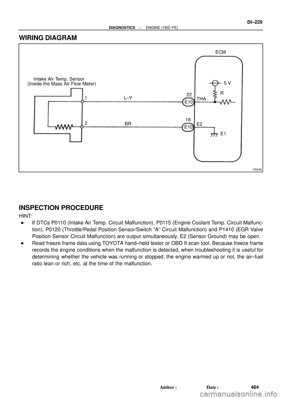
FI6448
Intake Air Temp. Sensor
(Inside the Mass Air Flow Meter)ECM
5 V
THA
E2
E1 1
2R
L±Y
BR
E10E1022
18
± DIAGNOSTICSENGINE (1MZ±FE)
DI±229
464 Author�: Date�:
WIRING DIAGRAM
INSPECTION PROCEDURE
HINT:
�If DTCs P0110 (Intake Air Temp. Circuit Malfunction), P0115 (Engine Coolant Temp. Circuit Malfunc-
tion), P0120 (Throttle/Pedal Position Sensor/Switch ºAº Circuit Malfunction) and P1410 (EGR Valve
Position Sensor Circuit Malfunction) are output simultaneously, E2 (Sensor Ground) may be open.
�Read freeze frame data using TOYOTA hand±held tester or OBD II scan tool. Because freeze frame
records the engine conditions when the malfunction is detected, when troubleshooting it is useful for
determining whether the vehicle was running or stopped, the engine warmed up or not, the air±fuel
ratio lean or rich, etc. at the time of the malfunction.
Page 2653 of 4770

DI±233
468 Author�: Date�:
DTC P0115 Engine Coolant Temp. Circuit Malfunction
CIRCUIT DESC")
FI6448
Engine Coolant Temp. SensorECM
5V
THW
E2
E1 2
1G±B
BR
E10
14
18
E10
± DIAGNOSTICSENGINE (1MZ±FE)
DI±233
468 Author�: Date�:
DTC P0115 Engine Coolant Temp. Circuit Malfunction
CIRCUIT DESCRIPTION
A thermistor built into the engine coolant temp. sensor changes the resistance value according to the engine
coolant temp.
The structure of the sensor and connection to the ECM is the same as in the intake air temp. circuit malfunc-
tion shown on page DI±228.
If the ECM detects the DTC P0115, it operates fail±safe function in which the engine coolant temperature
is assumed to be 80°C (176°F).
DTC No.Detection ItemTrouble Area
P0115Open or short in engine coolant temp. sensor circuit
�Open or short in engine coolant temp. sensor circuit
�Engine coolant temp. sensor
�ECM
HINT:
After confirming DTC P0115, use the OBD II scan tool or TOYOTA hand±held tester to confirm the engine
coolant temp. from CURRENT DATA.
Temperature DisplayedMalfunction
±40°C (±40°F)Open circuit
140°C (284°F) or moreShort circuit
WIRING DIAGRAM
INSPECTION PROCEDURE
HINT:
�If DTCs P0110 (Intake Air Temp. Circuit Malfunction), P0115 (Engine Coolant Temp. Circuit Malfunc-
tion), P0120 (Throttle/Pedal/Position Sensor/Switch ºAº Circuit Malfunction) and P1410 (EGR Valve
Position Sensor Circuit Malfunction) are output simultaneously, E2 (Sensor Ground) may be open.
�Read freeze frame data using TOYOTA hand±held tester or OBD II scan tool. Because freeze frame
records the engine conditions when the malfunction is detected, when troubleshooting it is useful for
determining whether the vehicle was running or stopped, the engine warmed up or not, the air±fuel
ratio lean or rich, etc. at the time of the malfunction.
DI07I±06
Page 2657 of 4770

DI±237
472 Author�: Date�:
DTC P0116 Engine Coolant Temp. Circuit Range/
Performance Problem
CIRCUIT DESCRIPTION
Refer to DTC P0115 (Engine Coolant Temp. Circuit Malfu")
± DIAGNOSTICSENGINE (1MZ±FE)
DI±237
472 Author�: Date�:
DTC P0116 Engine Coolant Temp. Circuit Range/
Performance Problem
CIRCUIT DESCRIPTION
Refer to DTC P0115 (Engine Coolant Temp. Circuit Malfunction) on page DI±233.
DTC No.DTC Detecting ConditionTrouble Area
If THW ±7°C (19.4°F), 20 min. or more after starting
engine, engine coolant temp. sensor value is 20°C (68°F) or
less
(2 trip detection logic)
If THW � ±7°C (19.4°F) and 10°C (50°F), 5 min. or more
after starting engine,
engine coolant temp. sensor value is 20°C (68°F) or less
(2 trip detection logic)
Engine coolant temp sensorP0116If THW � 10°C (50 °F), 2 min. or more after starting engine,
engine coolant temp. sensor value is 30°C (86°F)
(2 trip detection logic)�Engine coolant temp. sensor
�Cooling system
When THW � 35°C (95°F) or more and less than 60°C
(140°F), THA � ± 6.7°C (19.9°F) or more, when starting
engine , condition (a) and (b) continues:
(a) Vehicle speed is changing (Not stable)
(b) When starting engine, THW< 3°C (37.4°F)
(2 trip detection logic)
INSPECTION PROCEDURE
HINT:
�If DTCs P0115 (Engine Coolant Temp. Circuit Malfunction) and P0116 (Engine Coolant Temp. Circuit
Range/Performance) are output simultaneously, engine coolant temp. sensor circuit may be open.
Perform troubleshooting of DTC P0115 first.
�Read freeze frame data using TOYOTA hand±held tester or OBD II scan tool. Because freeze frame
records the engine conditions when the malfunction is detected, when troubleshooting it is useful for
determining whether the vehicle was running or stopped, the engine warmed up or not, the air±fuel
ratio lean or rich, etc. at the time of the malfunction.
1 Are there any other codes (besides DTC P0116) being output?
YES Go to relevant DTC chart.
NO
DI07J±06
Page 2659 of 4770

DI±239
474 Author�: Date�:
DTC P0120 Th")
P24296
ECM
Throttle Position
Sensor
VC
VTA1
E2
S05019
ECM
1
3
25 V
VC
VTA1
E2 Y
L
BR Throttle Position Sensor
E102
23
18 E10
E10
± DIAGNOSTICSENGINE (1MZ±FE)
DI±239
474 Author�: Date�:
DTC P0120 Throttle/Pedal Position Sensor/Switch ºAº
Circuit Malfunction
CIRCUIT DESCRIPTION
The throttle position sensor is mounted in the throttle body and
detects the throttle valve opening angle. When the throttle valve
is fully closed, a voltage of approximately 0.7 V is applied to ter-
minal VTA of the ECM. The voltage applied to the terminals VTA
of the ECM increases in proportion to the opening angle of the
throttle valve and becomes approximately 2.7 ~ 5.2 V when the
throttle valve is fully opened. the ECM judges the vehicle driving
conditions from these signals input from terminals VTA and
uses them as one of the conditions for deciding the air±fuel ratio
correction, power increase correction and fuel±cut control etc.
DTC No.DTC Detecting ConditionTrouble Area
P0120
Condition (a) or (b) continues:
(a) VTA
0.1 V
(b) VTA
4.9 V
�Open or short in throttle position sensor circuit
�Throttle position sensor
�ECM
HINT:
After confirming DTC P0120, use the OBD II scan tool or TOYOTA hand±held tester to confirm the throttle
valve opening percentage and closed throttle position switch condition.
Throttle valve opening position
expressed as percentage
Trouble Area
Throttle valve fully closedThrottle valve fully open
Trouble Area
0 %0 %VC line open
VTA line open or short
Approx. 100 %Approx. 100 %E2 line open
WIRING DIAGRAM
DI07K±06