Page 2607 of 4770
A03030A03451
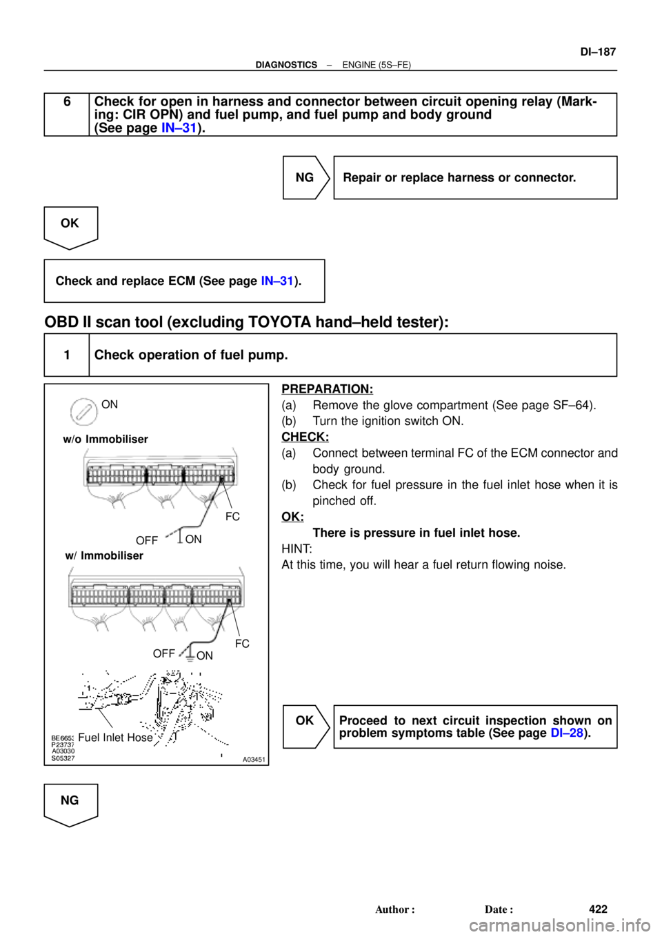
ON
FC
OFFON
Fuel Inlet Hose
FC
OFF
ON w/o Immobiliser
w/ Immobiliser
± DIAGNOSTICSENGINE (5S±FE)
DI±187
422 Author�: Date�:
6 Check for open in harness and connector between circuit opening relay (Mark-
ing: CIR OPN) and fuel pump, and fuel pump and body ground
(See page IN±31).
NG Repair or replace harness or connector.
OK
Check and replace ECM (See page IN±31).
OBD II scan tool (excluding TOYOTA hand±held tester):
1 Check operation of fuel pump.
PREPARATION:
(a) Remove the glove compartment (See page SF±64).
(b) Turn the ignition switch ON.
CHECK:
(a) Connect between terminal FC of the ECM connector and
body ground.
(b) Check for fuel pressure in the fuel inlet hose when it is
pinched off.
OK:
There is pressure in fuel inlet hose.
HINT:
At this time, you will hear a fuel return flowing noise.
OK Proceed to next circuit inspection shown on
problem symptoms table (See page DI±28).
NG
Page 2618 of 4770

433 Author�: Date�: �
The diagnosis system operates in normal mode
during normal vehicle use. It also has a check mode
for technicians to simulate malfunction sy")
DI±198
± DIAGNOSTICSENGINE (1MZ±FE)
433 Author�: Date�: �
The diagnosis system operates in normal mode
during normal vehicle use. It also has a check mode
for technicians to simulate malfunction symptoms
and troubleshoot. Most DTC use 2 trip detection
logic* to prevent erroneous detection, and ensure
thorough malfunction detection. By switching the
ECM to check mode when troubleshooting, the
technician can cause the MIL to light up for a mal-
function that is only detected once or momentarily
(TOYOTA hand±held tester only). (See page
DI±197)
�*2 trip detection logic:
When a malfunction is first detected, the malfunc-
tion is temporarily stored in the ECM memory. (1st
trip)
If the same malfunction is detected again during the second
drive test, this second detection causes the MIL to light up. (2nd
trip) (However, the IG switch must be turned OFF between the
1st trip and the 2nd trip.).
�Freeze frame data:
Freeze frame data records the engine condition
when a misfire (DTCs P0300 ~ P0306) or fuel trim
malfunction (DTCs P0171, P0172) or other mal-
function (first malfunction only), is detected.
Because freeze frame data records the engine
conditions (fuel system, calculated load, engine
coolant temperature, fuel trim, engine speed, ve-
hicle speed, etc.) when the malfunction is detected,
when troubleshooting it is useful for determining
whether the vehicle was running or stopped, the en-
gine warmed up or not, the air±fuel ratio lean or rich,
etc. at the time of the malfunction.
�Priorities for troubleshooting:
If troubleshooting priorities for multiple DTC are given in the ap-
plicable DTC chart, these should be followed.
If no instructions are given troubleshoot DTC according to the
following priorities.
(1) DTC other than fuel trim malfunction (DTCs P0171,
P0172), EGR (DTCs P0401, P0402) and misfire
(DTCs P0300 ~ P0306).
(2) Fuel trim malfunction (DTCs P0171, P0172) and
EGR (DTCs P0401, P0402).
(3) Misfire (DTCs P0300 ~ P0306).
Page 2622 of 4770

437 Author�: Date�:
4. FAIL±SAFE CHART
If any of the following codes is recorded, the ECM enters fail±safe mode.
DTC No.Fail±Safe OperationFail±Safe Deactiva")
DI±202
± DIAGNOSTICSENGINE (1MZ±FE)
437 Author�: Date�:
4. FAIL±SAFE CHART
If any of the following codes is recorded, the ECM enters fail±safe mode.
DTC No.Fail±Safe OperationFail±Safe Deactivation Conditions
P0100Ignition timing fixed at 10° BTDCReturned to normal condition
P0110Intake air temperature is fixed at 20°C (68°F)Returned to normal condition
P0115Engine coolant temperature is fixed at 80°C (176°F)Returned to normal condition
P0120VTA is fixed at 0°
The following condition must be repeated at least 2 times
consecutively
(a) Vehicle speed: 0km/h (0mph)
(b) VTA ��0.1 V and � 0.95 V
P0135
P0141
P0155The heater circuit in which an abnormality is detected is
turned offIgnition switch OFF
P0325
P0330Max. timing retardationIgnition switch OFF
P1300Fuel cutIGF signal is detected for 6 consecutive ignition
5. CHECK FOR INTERMITTENT PROBLEMS
TOYOTA HAND±HELD TESTER only:
By putting the vehicle's ECM in check mode, 1 trip detection logic is possible instead of 2 trip detection logic
and sensitivity to detect open circuits is increased. This makes it easier to detect intermittent problems.
(1) Clear the DTC (See page DI±197).
(2) Set the check mode (See page DI±197).
(3) Perform a simulation test (See page IN±21).
(4) Check the connector and terminal (See page IN±31).
(5) Handle the connector (See page IN±31).
6. BASIC INSPECTION
When the malfunction code is not confirmed in the DTC check, troubleshooting should be performed in the
order for all possible circuits to be considered as the causes of the problems. In many cases, by carrying
out the basic engine check shown in the following flow chart, the location causing the problem can be found
quickly and efficiently. Therefore, use of this check is essential in engine troubleshooting.
1 Is battery positive voltage 11 V or more when engine is stopped ?
NO Charge or replace battery.
YES
Page 2625 of 4770
P20186
± DIAGNOSTICSENGINE (1MZ±FE)
DI±205
440 Author�: Date�:
7 Check fuel pressure.
PREPARATION:
(a) Be sure that enough fuel is in the tank.
(b) Connect the TOYOTA hand±held tester to the DLC3.
(c) Turn the ignition switch ON and push the TOYOTA hand±
held tester main switch ON.
(d) Use ACTIVE TEST mode to operate the fuel pump.
(e) If you have no TOYOTA hand±held tester, connect the
positive (+) and negative (±) leads from the battery to the
fuel pump connector (See page SF±6).
CHECK:
Check that the pulsation damper screw rises up when the fuel
pump operates.
NG Proceed to page SF±6 and continue to
troubleshoot.
OK
Page 2626 of 4770
P23917
DI±206
± DIAGNOSTICSENGINE (1MZ±FE)
441 Author�: Date�:
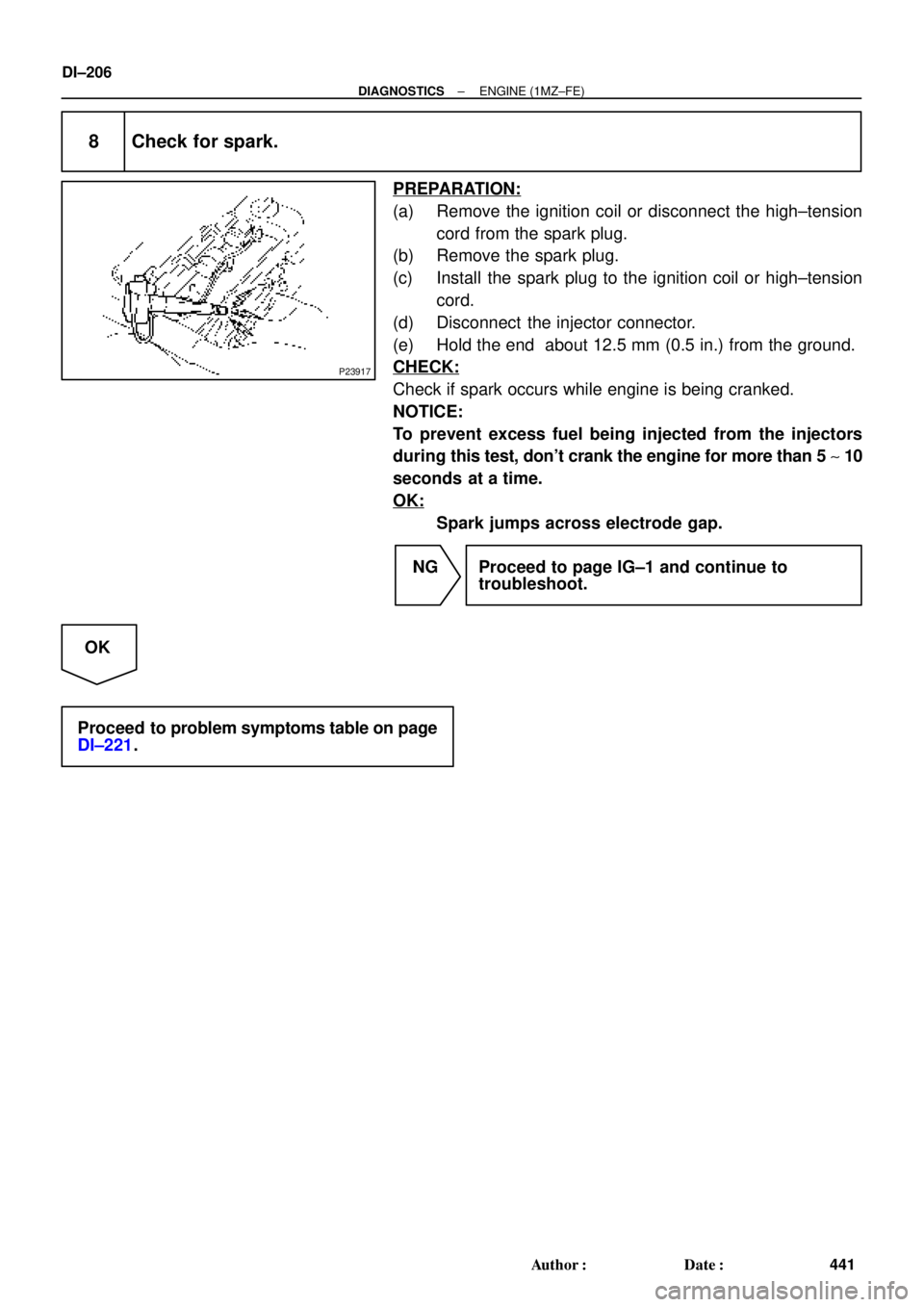
8 Check for spark.
PREPARATION:
(a) Remove the ignition coil or disconnect the high±tension
cord from the spark plug.
(b) Remove the spark plug.
(c) Install the spark plug to the ignition coil or high±tension
cord.
(d) Disconnect the injector connector.
(e) Hold the end about 12.5 mm (0.5 in.) from the ground.
CHECK:
Check if spark occurs while engine is being cranked.
NOTICE:
To prevent excess fuel being injected from the injectors
during this test, don't crank the engine for more than 5 ~ 10
seconds at a time.
OK:
Spark jumps across electrode gap.
NG Proceed to page IG±1 and continue to
troubleshoot.
OK
Proceed to problem symptoms table on page
DI±221.
Page 2627 of 4770

DI±207
442 Author�: Date�:
7. ENGINE OPERATING CONDITION
NOTICE:
The values given below for ºNormal Conditionº are representative values, so a vehicle may still be
no")
± DIAGNOSTICSENGINE (1MZ±FE)
DI±207
442 Author�: Date�:
7. ENGINE OPERATING CONDITION
NOTICE:
The values given below for ºNormal Conditionº are representative values, so a vehicle may still be
normal even if its value varies from those listed here. So do not decide whether a part is faulty or
not solely according to the ºNormal Conditionº here.
(a) CARB mandated signals.
TOYOTA hand±held tester displayMeasurement ItemNormal Condition*
FUEL SYS #1
Fuel System Bank 1
OPEN: Air±fuel ratio feedback stopped
CLOSED: Air±fuel ratio feedback operating
Idling after warming up: CLOSED
FUEL SYS #2
Fuel System Bank 2
OPEN: Air±fuel ratio feedback stopped
CLOSED: Air±fuel ratio feedback operating
Idling after warming up: CLOSED
CALC LOAD
Calculator Load:
Current intake air volume as a proportion of max.
intake air volumeIdling: 13.1 ~ 18.7%
Racing without load (2,500rpm): 11.7 ~ 17.3%
COOLANT TEMP.Engine Coolant Temp. Sensor ValueAfter warming up: 80 ~ 95°C (176 ~ 203°F)
SHORT FT #1Short±term Fuel Trim Bank 10 ± 20%
LONG FT #1Long±term Fuel Trim Bank 10 ± 20%
SHORT FT #2Short±term Fuel Trim Bank 20 ± 20%
LONG FT #2Long±term Fuel Trim Bank 20 ± 20%
ENGINE SPDEngine SpeedIdling: 650 ~ 750 rpm
VEHICLE SPDVehicle SpeedVehicle stopped: 0 km/h (0 mph)
IGN ADVANCEIgnition Advance:
Ignition Timing of Cylinder No. 1Idling: BTDC 10 ~ 25.0°
INTAKE AIRIntake Air Temp. Sensor ValueEquivalent to Ambient Temp.
MAFAir Flow Rate Through Mass Air Flow Meter
Idling: 3.3 ~ 4.7 gm/sec.
Racing without load (2,500 rpm):
10.4 ~ 15.4 gm/sec.
THROTTLE POS
Voltage Output of Throttle Position Sensor
Calculated as a percentage:
0 V "0%, 5 V "100%Throttle valve fully closed: 7 ~ 11 %
Throttle valve fully open: 65 ~ 75%
*: If no conditions are specifically stated for ºldlingº, it means the shift lever is at N or P position, the A/C switch
is OFF and all accessory switches are OFF.
Page 2628 of 4770

443 Author�: Date�:
TOYOTA hand±held tester displayMeasurement ItemNormal Condition*1
O2S B1, S1Voltage Output of Oxygen Sensor
Bank 1 Sensor 1Idling: 0.1 ~ 0")
DI±208
± DIAGNOSTICSENGINE (1MZ±FE)
443 Author�: Date�:
TOYOTA hand±held tester displayMeasurement ItemNormal Condition*1
O2S B1, S1Voltage Output of Oxygen Sensor
Bank 1 Sensor 1Idling: 0.1 ~ 0.9 V (0.56 ~ 0.76 V*2)
O2FT B1, S1Oxygen Sensor Fuel Trim Bank 1 Sensor 1
(Same as SHORT FT #1)0 ± 20%
O2S B1, S2Voltage Output of Oxygen Sensor
Bank 1 Sensor 2Driving 50 km/h (31 mph): 0.1 ~ 0.9 V
O2S B2, S1Voltage Output of Oxygen Sensor
Bank 2 Sensor 1Idling: 0.1 ~ 0.9 V (0.56 ~ 0.76 V*2)
O2FT B2, S1Oxygen Sensor Fuel Trim Bank 2 Sensor 1
(Same as SHORT FT #2)
0 ± 20%
A/FS B1, S1 *3Voltage Output of A/F Sensor Bank 1 Sensor 1Idling: 2.8 ~ 3.8 V
A/FS B2, S1 *3Voltage Output of A/F Sensor Bank 2 Sensor 1Idling: 2.8 ~ 3.8 V
A/FFT B1, S1 *3A/F Sensor Fuel Trim Bank 1 Sensor 1
(Same as SHORT FT #1)O ± 20%
A/FFT B2, S1 *3A/F Sensor Fuel Trim Bank 2 Sensor 1
(Same as SHORT FT #1)O ± 20%
*1: If no conditions are specifically stated for ºIdlingº, it means the shift lever is shift lever is at N or P position,
the A/C switch is OFF and all accessory switches are OFF.
*2: Only for California Specification vehicles, when you use the OBD II scan tool (excluding TOYOTA hand±
held tester).
*3: Only for California Specification vehicles, when you use the TOYOTA hand±held tester.
Page 2629 of 4770

DI±209
444 Author�: Date�:
(b) TOYOTA Enhanced Signals.
TOYOTA hand±held tester displayMeasurement ItemNormal Condition*
MISFIRE RPMEngine RPM for first misfire rangeM")
± DIAGNOSTICSENGINE (1MZ±FE)
DI±209
444 Author�: Date�:
(b) TOYOTA Enhanced Signals.
TOYOTA hand±held tester displayMeasurement ItemNormal Condition*
MISFIRE RPMEngine RPM for first misfire rangeMisfire 0: 0 rpm
MISFIRE LOADEngine load for first misfire rangeMisfire 0: 0 g/r
INJECTORFuel injection time for cylinder No.1Idling: 1.6 ~ 2.9 ms
IAC DUTY RATIOIntake Air Control Valve Duty Ratio
Opening ratio rotary solenoid type IAC valveIdling: 27 ~ 47 %
STARTER SIGStarter SignalCranking: ON
CTP SIGClosed Throttle Position SignalThrottle Fully Closed: ON
A/C SIGA/C Switch SignalA/C ON: ON
PNP SWPark/Neutral Position Switch SignalP or N position: ON
ELCTRCL LOAD SIGElectrical Load SignalDefogger switch ON: ON
STOP LIGHT SWStop Light Switch SignalStop light switch ON: ON
PS OIL PRESS SWPower Steering Oil Pressure Switch SignalTurn steering wheel: ON
FC IDLFuel Cut Idle: Fuel cut when throttle valve fully
closed, during decelerationFuel cut operating: ON
FC TAUFuel Cut TAU: Fuel cut during very light loadFuel cut operating: ON
CYL#1 ~ CYL#6Abnormal revolution variation for each cylinder0%
IGNITIONTotal number of ignition for every 1,000 revolu-
tions0 ~ 3,000
EGRT GASEGR Gas Temperature Sensor Value
EGR not operating:
Temperature between intake air temp. and
engine coolant temp.
INTAKE CTRL VSVIntake Air Control Valve VSV SignalVSV operating: ON
EGR SYSTEMEGR system operating conditionIdling: OFF
A/C CUT SIGA/C Cut SignalA/C S/W OFF: ON
FUEL PUMPFuel Pump SignalIdling: ON
EVAP (PURGE) VSVEVAP VSV SignalVSV operating: Above 30%
VAPOR PRESS VSVVapor Pressure VSV SignalVSV operating: ON (TANK)
*: If no conditions are specifically stated for ºldlingº, it means the shift lever is at N or P position, the A/C switch
is OFF and all accessory switches are OFF.