Page 3509 of 4770
COMPRESSION
EM±3
1289 Author�: Date�:
COMPRESSION
INSPECTION
HINT:
If there is lack of power, excessive oil consumption or poor fuel
ec")
EM04J±03
P19471Compression Gauge
± ENGINE MECHANICAL (1MZ±FE)COMPRESSION
EM±3
1289 Author�: Date�:
COMPRESSION
INSPECTION
HINT:
If there is lack of power, excessive oil consumption or poor fuel
economy, measure the compression pressure.
1. WARM UP AND STOP ENGINE
Allow the engine to warm up to normal operating temperature.
2. REMOVE IGNITION COILS AND HIGH±TENSION
CORDS (See page IG±7)
3. REMOVE SPARK PLUGS
Using a 16 mm plug wrench, remove the 6 spark plugs.
4. CHECK CYLINDER COMPRESSION PRESSURE
(a) Insert a compression gauge into the spark plug hole.
(b) Fully open the throttle.
(c) While cranking the engine, measure the compression
pressure.
HINT:
Always use a fully charged battery to obtain engine speed of
250 rpm or more.
(d) Repeat steps (a) through (c) for each cylinder.
NOTICE:
This measurement must be done in as short a time as pos-
sible.
Compression pressure:
1,500 kPa (15.3 kgf/cm
2, 218 psi)
Minimum pressure: 1,000 kPa (10.2 kgf/cm
2, 145 psi)
Difference between each cylinder:
100 kPa (1.0 kgf/cm
2, 15 psi) or less
(e) If the cylinder compression in 1 or more cylinders is low,
pour a small amount of engine oil into the cylinder through
the spark plug hole and repeat steps (a) through (c) for
cylinders with low compression.
�If adding oil helps the compression, it is likely that
the piston rings and/or cylinder bore are worn or
damaged.
�If pressure stays low, a valve may be sticking or
seating is improper, or there may be leakage past
the gasket.
5. REINSTALL SPARK PLUGS
6. INSTALL IGNITION COILS AND HIGH±TENSION
CORDS (See page IG±8)
Page 3510 of 4770
VALVE CLEARANCE
1290 Author�: Date�:
VALVE CLEARANCE
INSPECTION
HINT:
Inspect and adjust the val")
EM04K±04
P18805
P13074
RH EX
RH IN
LH IN
LH EX 13
6
23
1
6
2Front EM±4
± ENGINE MECHANICAL (1MZ±FE)VALVE CLEARANCE
1290 Author�: Date�:
VALVE CLEARANCE
INSPECTION
HINT:
Inspect and adjust the valve clearance when the engine is cold.
1. REMOVE RH FENDER APRON SEAL
2. DRAIN ENGINE COOLANT
3. REMOVE V±BANK COVER
(a) Using a 5 mm hexagon wrench, remove the 2 nuts.
(b) Disconnect the 2 clips, and remove the cover.
4. REMOVE HIGH±TENSION CODE SET
(See page IG±7)
5. REMOVE AIR INTAKE CHAMBER ASSEMBLY
(See page EM±32)
6. REMOVE IGNITION COILS
7. DISCONNECT RADIATOR HOSE FROM WATER
OUTLET
8. REMOVE CYLINDER HEAD COVERS
(See page EM±32)
9. SET NO.1 CYLINDER TO TDC/COMPRESSION
(a) Turn the crankshaft pulley, and align its groove with the
timing mark º0º of the No.1 timing belt cover.
(b) Check that the valve lifters on the No.1 (IN and EX) are
loose.
If not, turn the crankshaft 1 revolution (360°) and align the mark
as above.
10. INSPECT VALVE CLEARANCE
(a) Check only those valves indicated in the illustration.
(1) Using a feeler gauge, measure the clearance be-
tween the valve lifter and camshaft.
(2) Record out of specification valve clearance mea-
surements. They will be used later to determine the
required replacement adjusting shim.
Valve clearance (Cold):
Intake0.15 ± 0.25 mm (0.006 ± 0.010 in.)
Exhaust0.25 ± 0.35 mm (0.010 ± 0.014 in.)
Page 3522 of 4770
P18820
A01800
Clamp
Clamp
P18814
P18808
A05052
EM±16
± ENGINE MECHANICAL (1MZ±FE)TIMING BELT
1302 Author�: Date�:
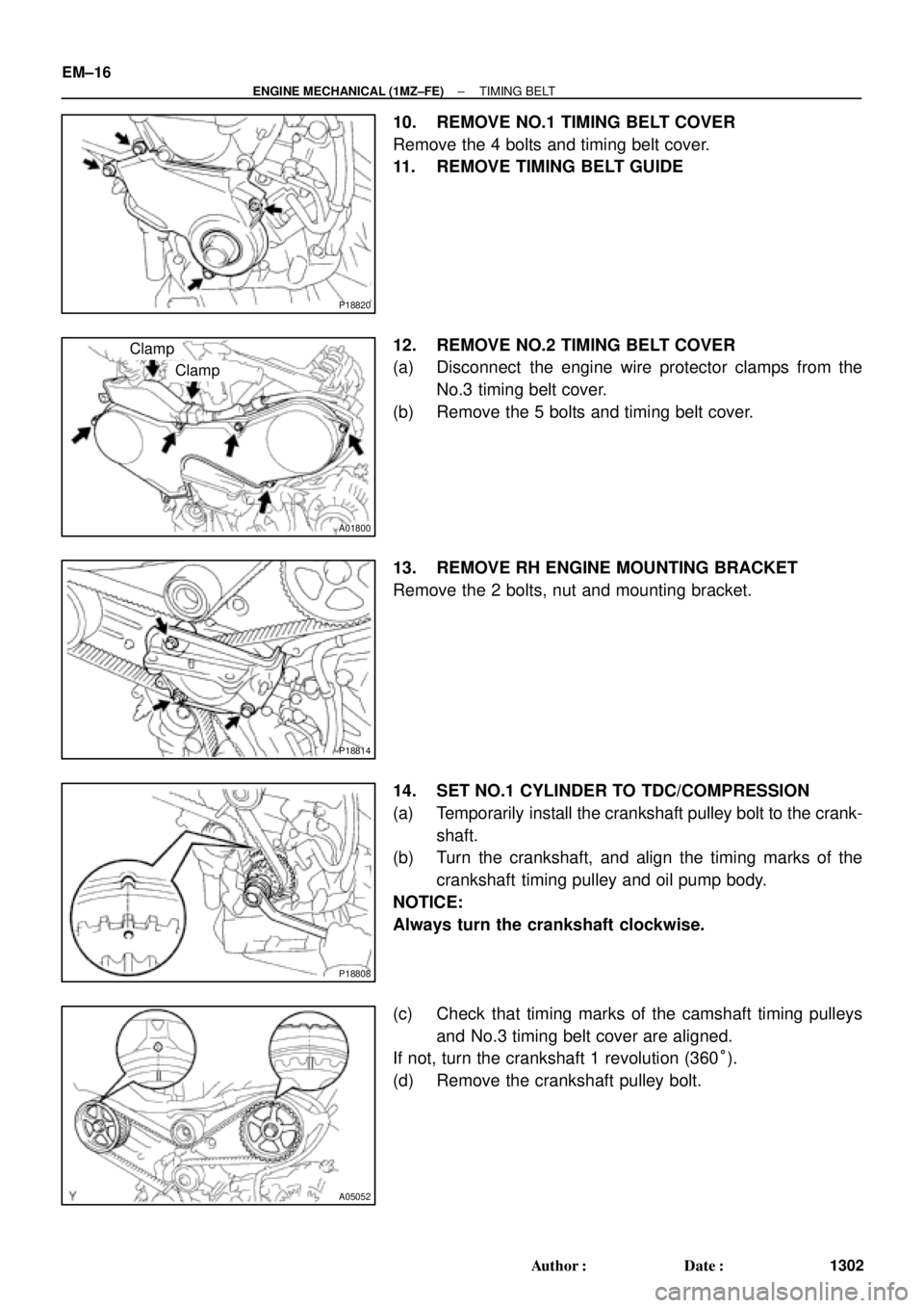
10. REMOVE NO.1 TIMING BELT COVER
Remove the 4 bolts and timing belt cover.
11. REMOVE TIMING BELT GUIDE
12. REMOVE NO.2 TIMING BELT COVER
(a) Disconnect the engine wire protector clamps from the
No.3 timing belt cover.
(b) Remove the 5 bolts and timing belt cover.
13. REMOVE RH ENGINE MOUNTING BRACKET
Remove the 2 bolts, nut and mounting bracket.
14. SET NO.1 CYLINDER TO TDC/COMPRESSION
(a) Temporarily install the crankshaft pulley bolt to the crank-
shaft.
(b) Turn the crankshaft, and align the timing marks of the
crankshaft timing pulley and oil pump body.
NOTICE:
Always turn the crankshaft clockwise.
(c) Check that timing marks of the camshaft timing pulleys
and No.3 timing belt cover are aligned.
If not, turn the crankshaft 1 revolution (360°).
(d) Remove the crankshaft pulley bolt.
Page 3528 of 4770
TIMING BELT
1308 Author�: Date�:
(c) Using SST, install the pulley bolt.
SST 09249±63010, 09960±1")
P20069
Fulcrum
Length
SSTSST RH
P12762
SST LH
P18811
A05063
SST
EM±22
± ENGINE MECHANICAL (1MZ±FE)TIMING BELT
1308 Author�: Date�:
(c) Using SST, install the pulley bolt.
SST 09249±63010, 09960±10010 (09962±01000,
09963±01000)
Torque: 88 N´m (900 kgf´cm, 65 ft´lbf)
HINT:
Use a torque wrench with a fulcrum length of 340 mm (13.39
in.).
5. INSTALL LH CAMSHAFT TIMING PULLEY
(a) Face the flange side of the timing pulley inward.
(b) Align the knock pin on the camshaft with the knock pin
groove of the timing pulley, and slide on the timing pulley.
(c) Using SST, install the pulley bolt.
SST 09960±10010 (09962±01000, 09963±01000)
Torque: 125 N´m (1,300 kgf´cm, 94 ft´lbf)
6. SET NO.1 CYLINDER TO TDC/COMPRESSION
(a) Crankshaft Timing Pulley Position:
Temporarily install the crankshaft pulley bolt to the crank-
shaft.
(b) Crankshaft Timing Pulley Position:
Turn the crankshaft, and align the timing marks of the
crankshaft timing pulley and oil pump body.
(c) Camshaft Timing Pulley Positions:
Using SST, turn the camshaft pulley, align the timing
marks of the timing pulley and No.3 timing belt cover.
SST 09960±10010 (09962±01000, 09963±01000)
Page 3598 of 4770
P12404
P12405
P12403
P12416
60°C
P12415
EM±92
± ENGINE MECHANICAL (1MZ±FE)CYLINDER BLOCK
1378 Author�: Date�:
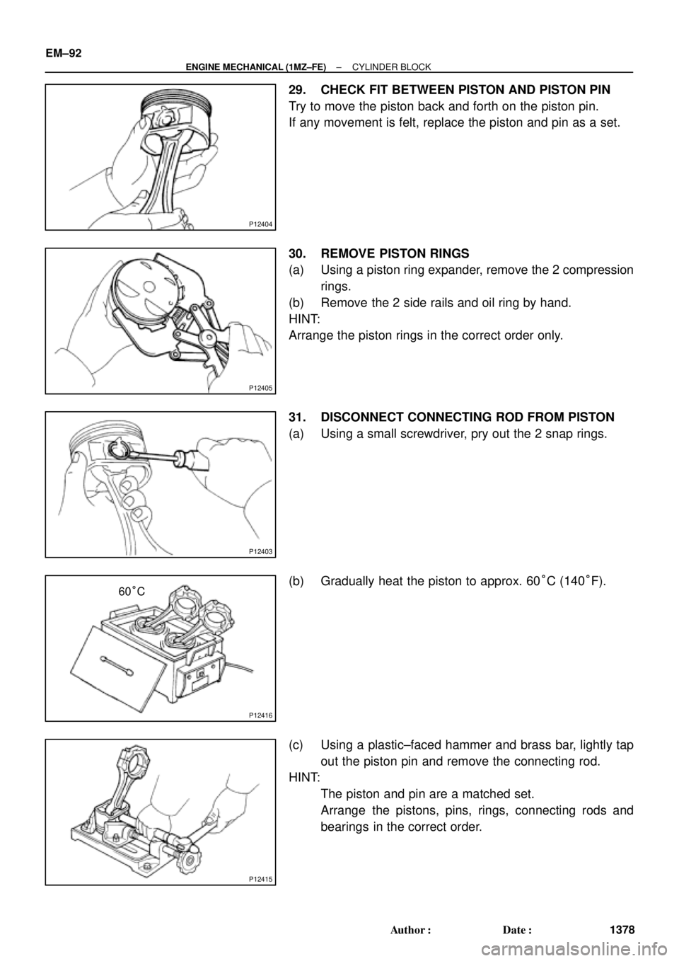
29. CHECK FIT BETWEEN PISTON AND PISTON PIN
Try to move the piston back and forth on the piston pin.
If any movement is felt, replace the piston and pin as a set.
30. REMOVE PISTON RINGS
(a) Using a piston ring expander, remove the 2 compression
rings.
(b) Remove the 2 side rails and oil ring by hand.
HINT:
Arrange the piston rings in the correct order only.
31. DISCONNECT CONNECTING ROD FROM PISTON
(a) Using a small screwdriver, pry out the 2 snap rings.
(b) Gradually heat the piston to approx. 60°C (140°F).
(c) Using a plastic±faced hammer and brass bar, lightly tap
out the piston pin and remove the connecting rod.
HINT:
�The piston and pin are a matched set.
�Arrange the pistons, pins, rings, connecting rods and
bearings in the correct order.
Page 3608 of 4770
S06043
Front Mark MAHLE Made
RH Piston
LH Piston(1 Cavity)
Front Mark
(Mold Mark)
Front Mark
(1 Cavity)
Front Mark
(Mold Mark)
Z09179
Code Mark
Code Mark No.1
No.2
S06058
RH Piston
Lower Side Rail
No.2
Compression
Front Mark
Expander
Upper Side Rail
No.1
Compression
Lower Side Rail
Upper Side RailFront Mark LH PistonNo.2
Compression
Expander
No.1
CompressionFront Markor EM±102
± ENGINE MECHANICAL (1MZ±FE)CYLINDER BLOCK
1388 Author�: Date�:
2. INSTALL PISTON RINGS
(a) Install the oil ring expander and 2 side rails by hand.
(b) Using a piston ring expander, install the 2 compression
rings with the code mark facing upward.
Code mark:
No.11R, T or G1
No.22R, 2T or G2
(c) Position the piston rings so that the ring ends are as
shown.
NOTICE:
Do not align the ring ends.
Page 3688 of 4770

± INTRODUCTIONFOR ALL OF VEHICLES
IN±17
17 Author�: Date�:
2. FOR VEHICLES EQUIPPED WITH A CATALYTIC CONVERTER
CAUTION:
If large amount of unburned gasoline flows into the converter, it may overheat and create a fire haz-
ard. To prevent this, observe the following precautions and explain them to your customer.
(a) Use only unleaded gasoline.
(b) Avoid prolonged idling.
Avoid running the engine at idle speed for more than 20 minutes.
(c) Avoid spark jump test.
(1) Perform spark jump test only when absolutely necessary. Perform this test as rapidly as possible.
(2) While testing, never race the engine.
(d) Avoid prolonged engine compression measurement.
Engine compression tests must be done as rapidly as possible.
(e) Do not run engine when fuel tank is nearly empty.
This may cause the engine to misfire and create an extra load on the converter.
(f) Avoid coasting with ignition turned off.
(g) Do not dispose of used catalyst along with parts contaminated with gasoline or oil.
3. IF VEHICLE IS EQUIPPED WITH MOBILE COMMUNICATION SYSTEM
For vehicles with mobile communication systems such as two±way radios and cellular telephones, observe
the following precautions.
(1) Install the antenna as far as possible away from the ECU and sensors of the vehicle's electronic
system.
(2) Install the antenna feeder at least 20 cm (7.87 in.) away from the ECU and sensors of the ve-
hicle's electronic systems. For details about ECU and sensors locations, refer to the section on
the applicable component.
(3) Avoid winding the antenna feeder together with other wiring as much as possible, and also avoid
running the antenna feeder parallel with other wire harnesses.
(4) Check that the antenna and feeder are correctly adjusted.
(5) Do not install powerful mobile communications system.
Page 3699 of 4770

IN±28± INTRODUCTIONHOW TO TROUBLESHOOT ECU CONTROLLED
SYSTEMS
28 Author�: Date�:
5. PROBLEM SYMPTOMS TABLE
The suspected circuits or parts for each problem symptom are shown in the table below. Use this table to
troubleshoot the problem when a ºNormalº code is displayed in the diagnostic trouble code check but the
problem is still occurring. Numbers in the table indicate the inspection order in which the circuits or parts
should be checked.
HINT:
When the problem is not detected by the diagnostic system even though the problem symptom is present,
it is considered that the problem is occurring outside the detection range of the diagnostic system, or that
the problem is occurring in a system other than the diagnostic system.
Symptom
Suspect AreaSee page
Engine does not crank (Does not start)
No initial combustion (Does not start)
No complete combustion (Does not start)1. Starter and starter relay
1. ECM power source circuit
2. Fuel pump control circuit
3. Engine control module (ECM)
1. Starter signal circuit
2. Fuel pump control circuit1. Fuel pump control circuitDI±147
DI±151
IN±29
PROBLEM SYMPTOMS TABLE
1. Compression
2. Fuel pump control circuit 1. A/C signal circuit
2. Fuel pump control circuit 1. A/C signal circuit (Compressor circuit)
2. ECM power source circuit 1. Starter signal circuit
2. Fuel pump control circuit1. Starter signal circuit
2. Fuel pump control circuit
3. Compression
idling) High engine idle speed (Poor idling) Hot engine Cold engine (Difficult to start)Engine cranks normally (Difficult to start)
AC±88 DI±144
DI±151
EM±3 DI±151
� Problem Symptom� Page
Indicates the page where the flow chart for each circuit
is located.
� Circuit Inspection, Inspection Order
Indicates the circuit which needs to be checked for each problem
symptom. Check in the order indicated by the numbers.
� Circuit or Part Name
Indicates the circuit or part which needs to be checked.
ST±2
ST±17
DI±144
DI±151
DI±144
DI±151

Front Mark
(Mold Mark)
Front Mark
(1 Cavity)
Front Mark
(Mold Mark)
Z09179
Code Mark
Code Mark No.1
No.2
S06058
RH Piston
Lower Side Rail
No.")