Page 2641 of 4770
DI07E±06
± DIAGNOSTICSENGINE (1MZ±FE)
DI±221
456 Author�: Date�:
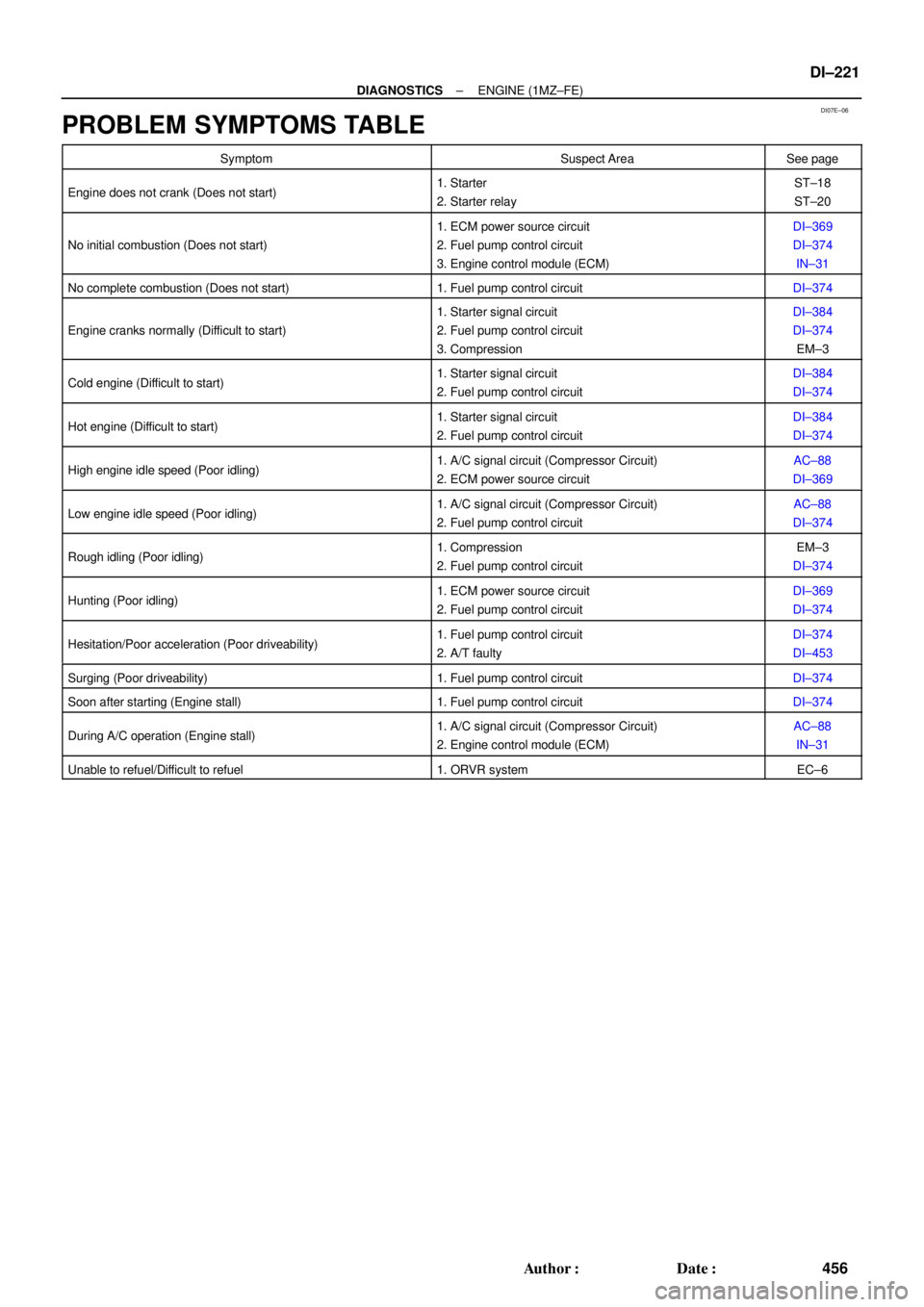
PROBLEM SYMPTOMS TABLE
SymptomSuspect AreaSee page
Engine does not crank (Does not start)1. Starter
2. Starter relayST±18
ST±20
No initial combustion (Does not start)
1. ECM power source circuit
2. Fuel pump control circuit
3. Engine control module (ECM)DI±369
DI±374
IN±31
No complete combustion (Does not start)1. Fuel pump control circuitDI±374
Engine cranks normally (Difficult to start)
1. Starter signal circuit
2. Fuel pump control circuit
3. CompressionDI±384
DI±374
EM±3
Cold engine (Difficult to start)1. Starter signal circuit
2. Fuel pump control circuitDI±384
DI±374
Hot engine (Difficult to start)1. Starter signal circuit
2. Fuel pump control circuitDI±384
DI±374
High engine idle speed (Poor idling)1. A/C signal circuit (Compressor Circuit)
2. ECM power source circuitAC±88
DI±369
Low engine idle speed (Poor idling)1. A/C signal circuit (Compressor Circuit)
2. Fuel pump control circuitAC±88
DI±374
Rough idling (Poor idling)1. Compression
2. Fuel pump control circuitEM±3
DI±374
Hunting (Poor idling)1. ECM power source circuit
2. Fuel pump control circuitDI±369
DI±374
Hesitation/Poor acceleration (Poor driveability)1. Fuel pump control circuit
2. A/T faultyDI±374
DI±453
Surging (Poor driveability)1. Fuel pump control circuitDI±374
Soon after starting (Engine stall)1. Fuel pump control circuitDI±374
During A/C operation (Engine stall)1. A/C signal circuit (Compressor Circuit)
2. Engine control module (ECM)AC±88
IN±31
Unable to refuel/Difficult to refuel1. ORVR systemEC±6
Page 2696 of 4770

DI±276
± DIAGNOSTICSENGINE (1MZ±FE)
511 Author�: Date�:
DTC P0300 Random/Multiple Cylinder Misfire Detected
DTC P0301 Cylinder 1 Misfire Detected
DTC P0302 Cylinder 2 Misfire Detected
DTC P0303 Cylinder 3 Misfire Detected
DTC P0304 Cylinder 4 Misfire Detected
DTC P0305 Cylinder 5 Misfire Detected
DTC P0306 Cylinder 6 Misfire Detected
CIRCUIT DESCRIPTION
Misfire: The ECM uses the crankshaft position sensor and camshaft position sensor to monitor changes in
the crankshaft rotation for each cylinder.
The ECM counts the number of times the engine speed change rate indicates that misfire has occurred.
When the misfire rate equals or exceeds the count indicating that the engine condition has deteriorated, the
MIL lights up.
If the misfire rate is high enough and the driving conditions will cause catalyst overheating, the MIL blinks
when misfiring occurs.
DTC No.DTC Detecting ConditionTrouble Area
P0300Misfiring of random cylinders is detected during any
particular 200 or 1,000 revolutions�Ignition system
�Injector
�Fuel line pressure
P0301
P0302
P0303For any particular 200 revolutions for engine, misfiring is de-
tected which can cause catalyst overheating
(This causes MIL to blink)
�EGR
�Compression pressure
�Valve clearance not to specification
�Valve timing
�Mass air flow meterP0303
P0304
P0305
P0306For any particular 1,000 revolutions of engine, misfiring is de-
tected which causes a deterioration in emission
(2 trip detection logic)
�Mass air flow meter
�Engine coolant temp. sensor
�Open or short in engine wire
�Connector connection
�ECM
DI07S±07
Page 2702 of 4770
DI±282
± DIAGNOSTICSENGINE (1MZ±FE)
517 Author�: Date�:
8 Check mass air flow meter and engine coolant temp. sensor
(See pages SF±35, SF±63).
NG Repair or replace.
OK
Check compression pressure, valve
clearance and valve timing.
Page 3395 of 4770
EM07Y±05
S05312
Compression
Gauge
± ENGINE MECHANICAL (5S±FE)COMPRESSION
EM±3
1175 Author�: Date�:
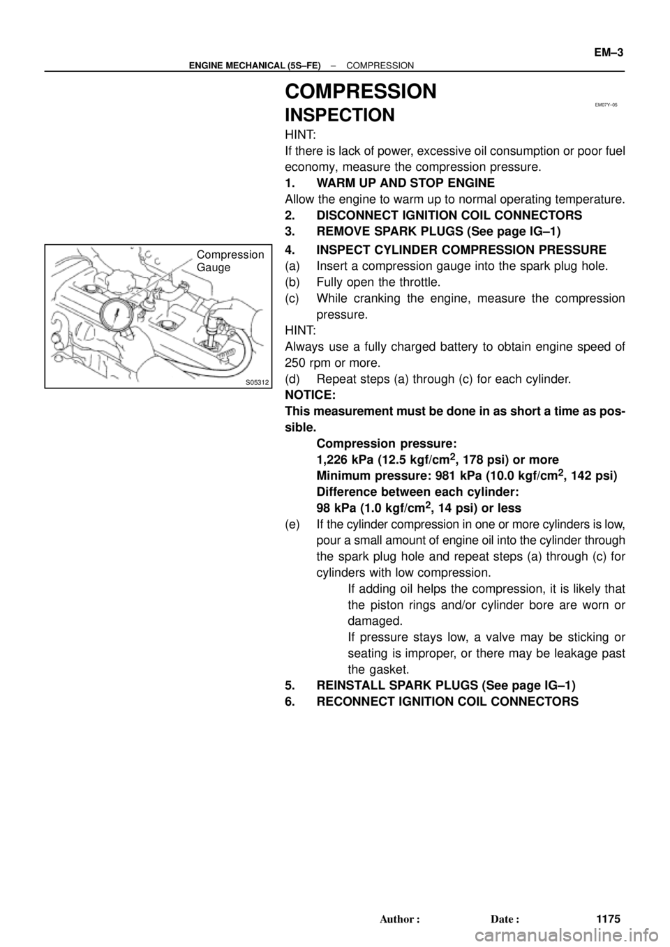
COMPRESSION
INSPECTION
HINT:
If there is lack of power, excessive oil consumption or poor fuel
economy, measure the compression pressure.
1. WARM UP AND STOP ENGINE
Allow the engine to warm up to normal operating temperature.
2. DISCONNECT IGNITION COIL CONNECTORS
3. REMOVE SPARK PLUGS (See page IG±1)
4. INSPECT CYLINDER COMPRESSION PRESSURE
(a) Insert a compression gauge into the spark plug hole.
(b) Fully open the throttle.
(c) While cranking the engine, measure the compression
pressure.
HINT:
Always use a fully charged battery to obtain engine speed of
250 rpm or more.
(d) Repeat steps (a) through (c) for each cylinder.
NOTICE:
This measurement must be done in as short a time as pos-
sible.
Compression pressure:
1,226 kPa (12.5 kgf/cm
2, 178 psi) or more
Minimum pressure: 981 kPa (10.0 kgf/cm
2, 142 psi)
Difference between each cylinder:
98 kPa (1.0 kgf/cm
2, 14 psi) or less
(e) If the cylinder compression in one or more cylinders is low,
pour a small amount of engine oil into the cylinder through
the spark plug hole and repeat steps (a) through (c) for
cylinders with low compression.
�If adding oil helps the compression, it is likely that
the piston rings and/or cylinder bore are worn or
damaged.
�If pressure stays low, a valve may be sticking or
seating is improper, or there may be leakage past
the gasket.
5. REINSTALL SPARK PLUGS (See page IG±1)
6. RECONNECT IGNITION COIL CONNECTORS
Page 3396 of 4770
EM07Z±03
S05289
(c)
(d) (e)
S05590
Turn
P03443
1 11 122
33 EM±4
± ENGINE MECHANICAL (5S±FE)VALVE CLEARANCE
1176 Author�: Date�:
VALVE CLEARANCE
INSPECTION
HINT:
Inspect and adjust the valve clearance when the engine is cold.
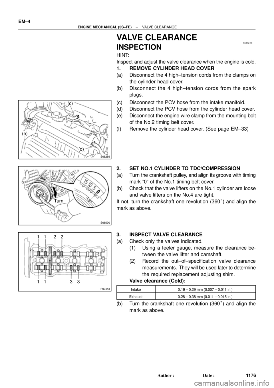
1. REMOVE CYLINDER HEAD COVER
(a) Disconnect the 4 high±tension cords from the clamps on
the cylinder head cover.
(b) Disconnect the 4 high±tension cords from the spark
plugs.
(c) Disconnect the PCV hose from the intake manifold.
(d) Disconnect the PCV hose from the cylinder head cover.
(e) Disconnect the engine wire clamp from the mounting bolt
of the No.2 timing belt cover.
(f) Remove the cylinder head cover. (See page EM±33)
2. SET NO.1 CYLINDER TO TDC/COMPRESSION
(a) Turn the crankshaft pulley, and align its groove with timing
mark º0º of the No.1 timing belt cover.
(b) Check that the valve lifters on the No.1 cylinder are loose
and valve lifters on the No.4 are tight.
If not, turn the crankshaft one revolution (360°) and align the
mark as above.
3. INSPECT VALVE CLEARANCE
(a) Check only the valves indicated.
(1) Using a feeler gauge, measure the clearance be-
tween the valve lifter and camshaft.
(2) Record the out±of±specification valve clearance
measurements. They will be used later to determine
the required replacement adjusting shim.
Valve clearance (Cold):
Intake0.19 ± 0.29 mm (0.007 ± 0.011 in.)
Exhaust0.28 ± 0.38 mm (0.011 ± 0.015 in.)
(b) Turn the crankshaft one revolution (360°) and align the
mark as above.
Page 3410 of 4770
S05587
Turn
S05580
A02585
S05583
Pry
Move
S05593
SSTSST EM±18
± ENGINE MECHANICAL (5S±FE)TIMING BELT
1190 Author�: Date�:
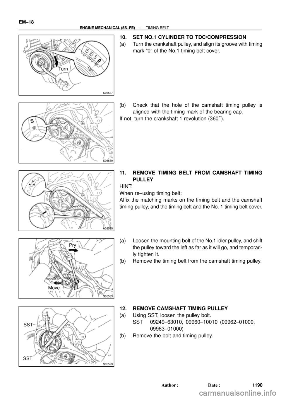
10. SET NO.1 CYLINDER TO TDC/COMPRESSION
(a) Turn the crankshaft pulley, and align its groove with timing
mark º0º of the No.1 timing belt cover.
(b) Check that the hole of the camshaft timing pulley is
aligned with the timing mark of the bearing cap.
If not, turn the crankshaft 1 revolution (360°).
11. REMOVE TIMING BELT FROM CAMSHAFT TIMING
PULLEY
HINT:
When re±using timing belt:
Affix the matching marks on the timing belt and the camshaft
timing pulley, and the timing belt and the No. 1 timing belt cover.
(a) Loosen the mounting bolt of the No.1 idler pulley, and shift
the pulley toward the left as far as it will go, and temporari-
ly tighten it.
(b) Remove the timing belt from the camshaft timing pulley.
12. REMOVE CAMSHAFT TIMING PULLEY
(a) Using SST, loosen the pulley bolt.
SST 09249±63010, 09960±10010 (09962±01000,
09963±01000)
(b) Remove the bolt and timing pulley.
Page 3417 of 4770
A02591
S05588
SSTSST
S05592
SST
SST
Fulcrum
Length
S05587
Turn
± ENGINE MECHANICAL (5S±FE)TIMING BELT
EM±25
1197 Author�: Date�:
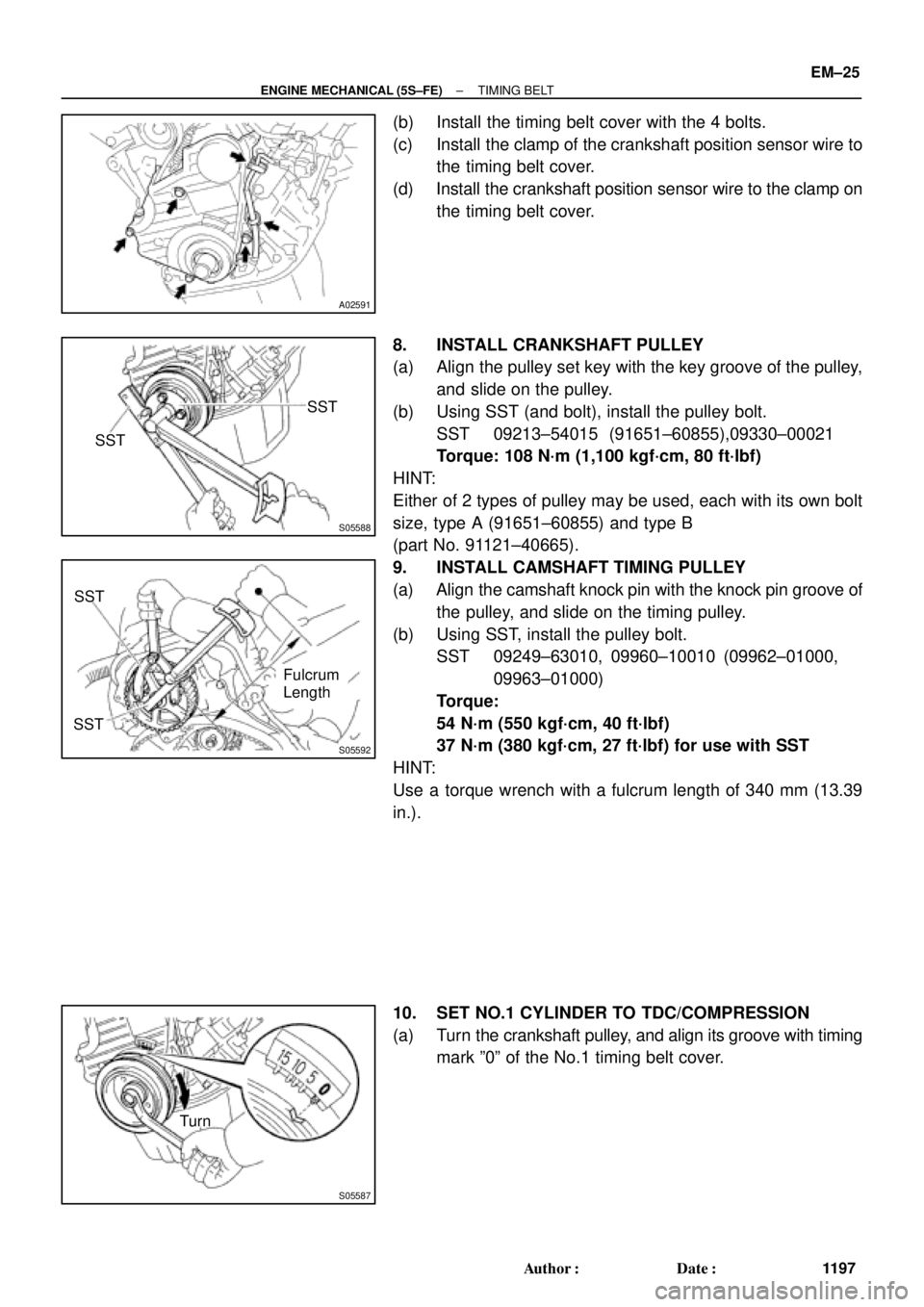
(b) Install the timing belt cover with the 4 bolts.
(c) Install the clamp of the crankshaft position sensor wire to
the timing belt cover.
(d) Install the crankshaft position sensor wire to the clamp on
the timing belt cover.
8. INSTALL CRANKSHAFT PULLEY
(a) Align the pulley set key with the key groove of the pulley,
and slide on the pulley.
(b) Using SST (and bolt), install the pulley bolt.
SST 09213±54015 (91651±60855),09330±00021
Torque: 108 N´m (1,100 kgf´cm, 80 ft´lbf)
HINT:
Either of 2 types of pulley may be used, each with its own bolt
size, type A (91651±60855) and type B
(part No. 91121±40665).
9. INSTALL CAMSHAFT TIMING PULLEY
(a) Align the camshaft knock pin with the knock pin groove of
the pulley, and slide on the timing pulley.
(b) Using SST, install the pulley bolt.
SST 09249±63010, 09960±10010 (09962±01000,
09963±01000)
Torque:
54 N´m (550 kgf´cm, 40 ft´lbf)
37 N´m (380 kgf´cm, 27 ft´lbf) for use with SST
HINT:
Use a torque wrench with a fulcrum length of 340 mm (13.39
in.).
10. SET NO.1 CYLINDER TO TDC/COMPRESSION
(a) Turn the crankshaft pulley, and align its groove with timing
mark º0º of the No.1 timing belt cover.
Page 3500 of 4770
A06588
No.1
No.2Code Mark
Code Mark
A07351
Upper Side Rail
ExpanderFront
Mark
(Cavity) No.1
Compression
Ring
No.2
Compression
RingLower Side Rail
P
P00797
P05533
22.9 mm
19.2 mm Others
No.3
P05353
EM±108
± ENGINE MECHANICAL (5S±FE)CYLINDER BLOCK
1280 Author�: Date�:
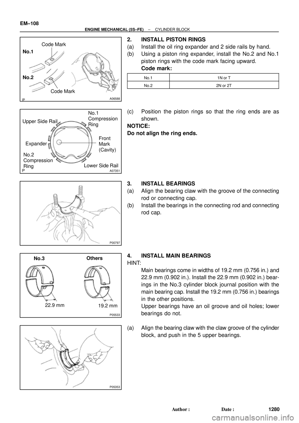
2. INSTALL PISTON RINGS
(a) Install the oil ring expander and 2 side rails by hand.
(b) Using a piston ring expander, install the No.2 and No.1
piston rings with the code mark facing upward.
Code mark:
No.11N or T
No.22N or 2T
(c) Position the piston rings so that the ring ends are as
shown.
NOTICE:
Do not align the ring ends.
3. INSTALL BEARINGS
(a) Align the bearing claw with the groove of the connecting
rod or connecting cap.
(b) Install the bearings in the connecting rod and connecting
rod cap.
4. INSTALL MAIN BEARINGS
HINT:
�Main bearings come in widths of 19.2 mm (0.756 in.) and
22.9 mm (0.902 in.). Install the 22.9 mm (0.902 in.) bear-
ings in the No.3 cylinder block journal position with the
main bearing cap. Install the 19.2 mm (0.756 in.) bearings
in the other positions.
�Upper bearings have an oil groove and oil holes; lower
bearings do not.
(a) Align the bearing claw with the claw groove of the cylinder
block, and push in the 5 upper bearings.