Page 122 of 447

7B-80 AUTOMATIC TRANSMISSION (4 A/T)
12) Disconnect couplers from solenoid valves, and transmission
temperature sensor.
Remove transmission temperature sensor.
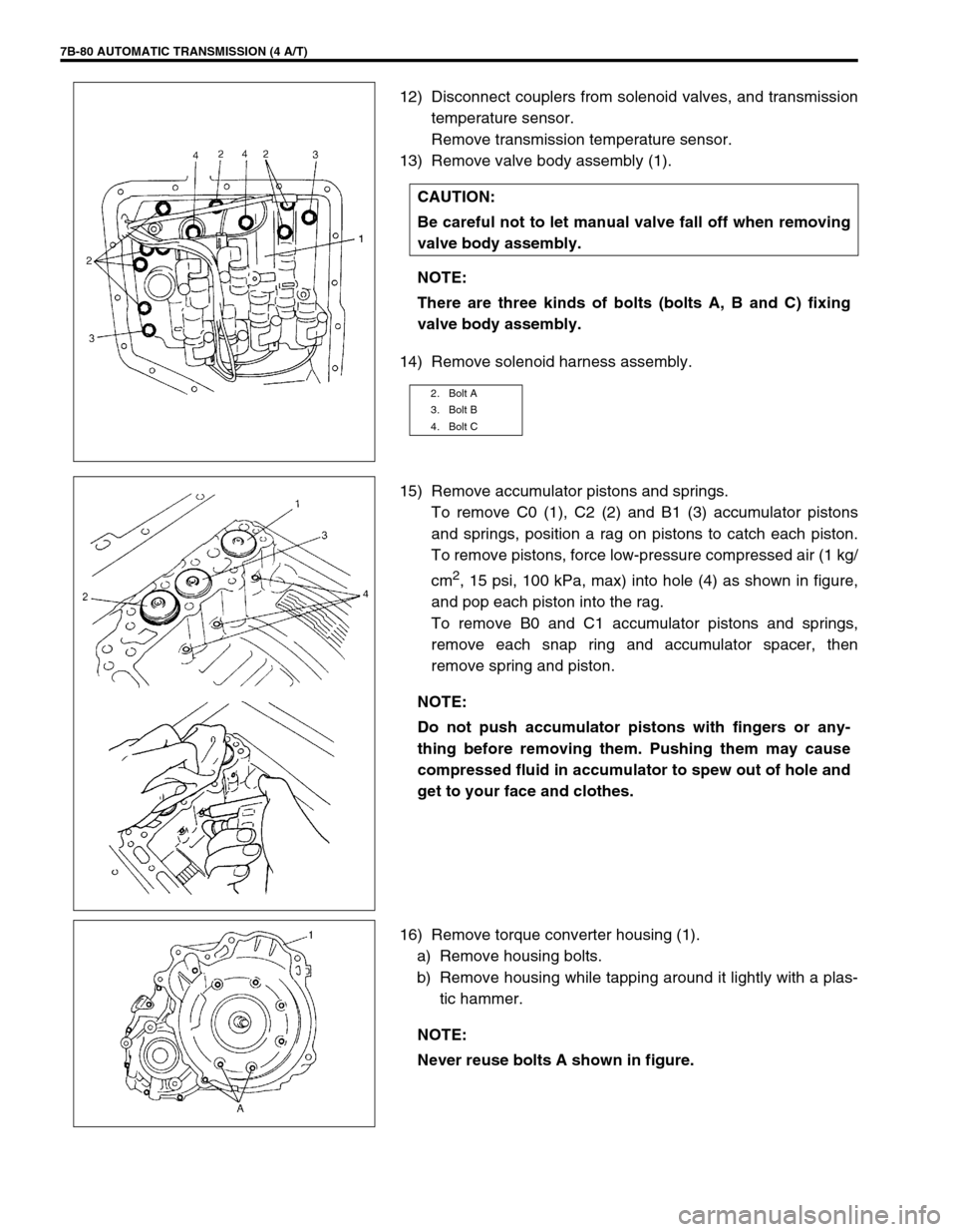
13) Remove valve body assembly (1).
14) Remove solenoid harness assembly.
15) Remove accumulator pistons and springs.
To remove C0 (1), C2 (2) and B1 (3) accumulator pistons
and springs, position a rag on pistons to catch each piston.
To remove pistons, force low-pressure compressed air (1 kg/
cm
2, 15 psi, 100 kPa, max) into hole (4) as shown in figure,
and pop each piston into the rag.
To remove B0 and C1 accumulator pistons and springs,
remove each snap ring and accumulator spacer, then
remove spring and piston.
16) Remove torque converter housing (1).
a) Remove housing bolts.
b) Remove housing while tapping around it lightly with a plas-
tic hammer. CAUTION:
Be careful not to let manual valve fall off when removing
valve body assembly.
NOTE:
There are three kinds of bolts (bolts A, B and C) fixing
valve body assembly.
2. Bolt A
3. Bolt B
4. Bolt C
NOTE:
Do not push accumulator pistons with fingers or any-
thing before removing them. Pushing them may cause
compressed fluid in accumulator to spew out of hole and
get to your face and clothes.
NOTE:
Never reuse bolts A shown in figure.
Page 130 of 447

7B-88 AUTOMATIC TRANSMISSION (4 A/T)
DISASSEMBLY/ASSEMBLY OF SUBASSEMBLY
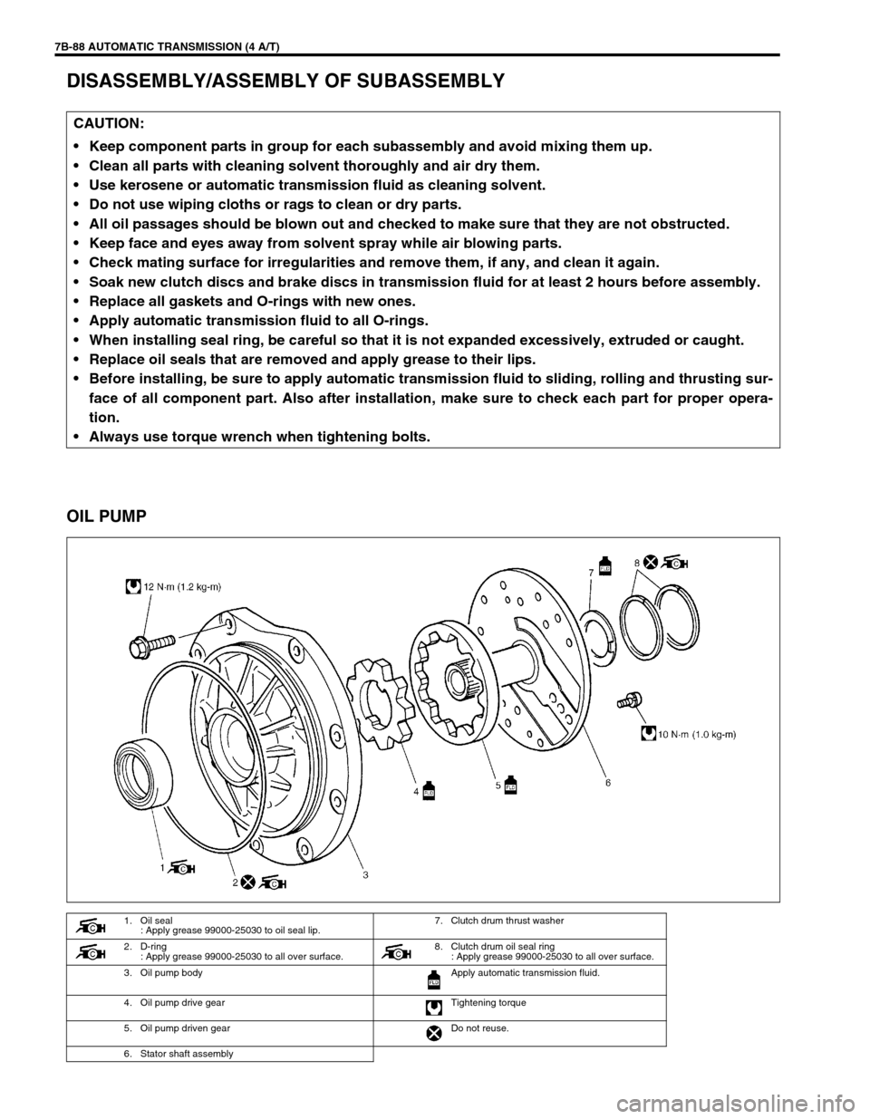
OIL PUMP
CAUTION:
Keep component parts in group for each subassembly and avoid mixing them up.
Clean all parts with cleaning solvent thoroughly and air dry them.
Use kerosene or automatic transmission fluid as cleaning solvent.
Do not use wiping cloths or rags to clean or dry parts.
All oil passages should be blown out and checked to make sure that they are not obstructed.
Keep face and eyes away from solvent spray while air blowing parts.
Check mating surface for irregularities and remove them, if any, and clean it again.
Soak new clutch discs and brake discs in transmission fluid for at least 2 hours before assembly.
Replace all gaskets and O-rings with new ones.
Apply automatic transmission fluid to all O-rings.
When installing seal ring, be careful so that it is not expanded excessively, extruded or caught.
Replace oil seals that are removed and apply grease to their lips.
Before installing, be sure to apply automatic transmission fluid to sliding, rolling and thrusting sur-
face of all component part. Also after installation, make sure to check each part for proper opera-
tion.
Always use torque wrench when tightening bolts.
1. Oil seal
: Apply grease 99000-25030 to oil seal lip.7. Clutch drum thrust washer
2. D-ring
: Apply grease 99000-25030 to all over surface. 8. Clutch drum oil seal ring
: Apply grease 99000-25030 to all over surface.
3. Oil pump body Apply automatic transmission fluid.
4. Oil pump drive gear Tightening torque
5. Oil pump driven gear Do not reuse.
6. Stator shaft assembly
Page 132 of 447
7B-90 AUTOMATIC TRANSMISSION (4 A/T)
ASSEMBLY
1) Install pump body oil seal (1)
Use special tool and hammer to install it, and then apply
grease to its lip portion.
Special tool
(A) : 09913-85210
“A”: Grease 99000-25030
2) Install driven gear and drive gear to pump body (2) after
applying A/T fluid to gears.
3) Install stator shaft assembly to pump body and tighten 11
pump cover bolts to specification.
Tightening torque
Oil pump cover bolts (a) : 10 N·m (1.0 kg-m, 7.5 lb-ft)
4) Install 2 new oil seal rings to stator shaft.
5) Apply grease to 2 oil seal rings.
6) Install new D-ring to which grease is applied and make sure
that it is not twisted or extruded.
7) Check drive gear for smooth rotation.
Page 153 of 447
AUTOMATIC TRANSMISSION (4 A/T) 7B-111
3) Assemble lower valve body with gaskets and plate over
upper valve body.
First tighten bolts A then the other bolts.
Tightening torque
Valve body bolts (a) : 5.5 N·m (0.55 kg-m, 4.0 lb-ft)
4) Install manual valve to valve body assembly.NOTE:
Be careful not to fall steel balls off.
There are four kinds of bolts fixing upper and lower
valve body. Refer to the table below for the bolt specifi-
cations.
Bolt Length “a”Pieces
A 20 mm (0.79 in.) 2
B 23 mm (0.91 in.) 2
C 29.5 mm (1.16 in.) 3
D 42 mm (1.65 in.) 5
1. Bolt A 3. Bolt C
2. Bolt B 4. Bolt D
Page 154 of 447
7B-112 AUTOMATIC TRANSMISSION (4 A/T)
DIFFERENTIAL ASSEMBLY
Servicing procedure for differential assembly is similar to that for manual transmission. Refer to Section 7A of
this manual for adjustment procedure.
DISASSEMBLY
1) Remove R bearing and then speed sensor rotor using spe-
cial tool and puller.
Special tool
(A) : 09925-88210
2) Hold differential assembly with soft jawed vise, remove final
gear (1).
1. Differential pinion 7. Differential right side bearing (R bearing) 13. Pinion shaft pin
2. Differential gear
8. Speedometer sensor rotor Apply automatic transmission fluid.
3. Washer (for pinion)
9. Differential case Tightening torque
4. Pinion shaft
10. Final gear Do not reuse.
5. Washer (for gear) 11. Bolt
6. Differential side oil seal
: Apply grease 99000-25030 to oil seal lip.
12. Differential left side bearing (L bearing)
1. Differential gear assembly
Page 156 of 447

7B-114 AUTOMATIC TRANSMISSION (4 A/T)
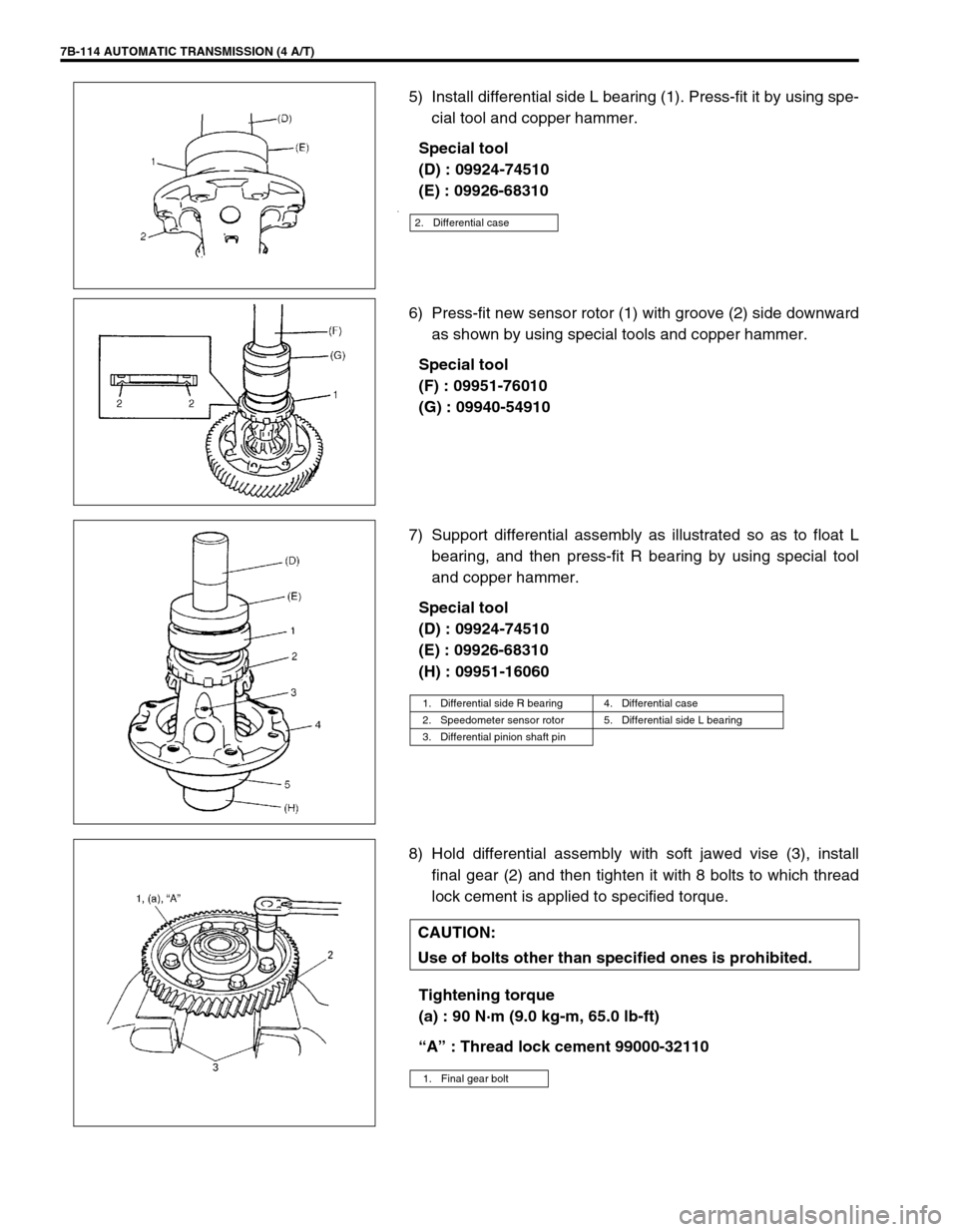
5) Install differential side L bearing (1). Press-fit it by using spe-
cial tool and copper hammer.
Special tool
(D) : 09924-74510
(E) : 09926-68310
.
6) Press-fit new sensor rotor (1) with groove (2) side downward
as shown by using special tools and copper hammer.
Special tool
(F) : 09951-76010
(G) : 09940-54910
7) Support differential assembly as illustrated so as to float L
bearing, and then press-fit R bearing by using special tool
and copper hammer.
Special tool
(D) : 09924-74510
(E) : 09926-68310
(H) : 09951-16060
8) Hold differential assembly with soft jawed vise (3), install
final gear (2) and then tighten it with 8 bolts to which thread
lock cement is applied to specified torque.
Tightening torque
(a) : 90 N·m (9.0 kg-m, 65.0 lb-ft)
“A” : Thread lock cement 99000-32110
2. Differential case
1. Differential side R bearing 4. Differential case
2. Speedometer sensor rotor 5. Differential side L bearing
3. Differential pinion shaft pin
CAUTION:
Use of bolts other than specified ones is prohibited.
1. Final gear bolt
Page 158 of 447
7B-116 AUTOMATIC TRANSMISSION (4 A/T)
Inner race (1) can rotate only one direction shown in figure.
Fit 2 protrusions of washer to holes of planetary sun gear
No.1.
TORQUE CONVERTER HOUSING
DISASSEMBLY
1) Remove oil seal (1).
2) Remove counter bearing (1) using special tools.
Special tool
(A) : 09930-30102
(B) : 09923-74510
ASSEMBLY
1) Install counter bearing to torque converter housing.
Use special tools and a hammer to press fit the bearing to
torque converter housing.
Special tool
(D) : 09924-74510
(E) : 09944-68510
Page 159 of 447
AUTOMATIC TRANSMISSION (4 A/T) 7B-117
2) Install new oil seal to torque converter housing.
Use special tool to press-fit oil seal until the oil seal end face
is flush with torque converter housing end face.
Special tool
(F) : 09940-53111
TRANSMISSION CASE
DISASSEMBLY
1) Remove oil seal (1).
2) Remove counter bearing (1) using special tools.
Special tool
(A) : 09930-30102
(C) : 09941-64511
ASSEMBLY
1) Install counter bearing using special tools.
Special tool
(D) : 09924-74510
(E) : 09944-68510