Page 105 of 447

AUTOMATIC TRANSMISSION (4 A/T) 7B-63
INPUT SHAFT SPEED SENSOR
INSPECTION
1) Disconnect negative cable at battery.
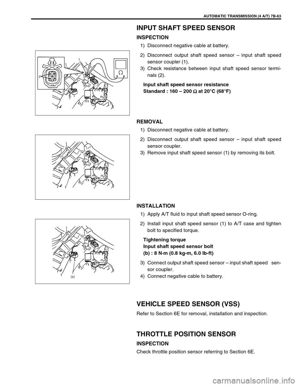
2) Disconnect output shaft speed sensor – input shaft speed
sensor coupler (1).
3) Check resistance between input shaft speed sensor termi-
nals (2).
Input shaft speed sensor resistance
Standard : 160 – 200
Ω
ΩΩ Ω at 20°C (68°F)
REMOVAL
1) Disconnect negative cable at battery.
2) Disconnect output shaft speed sensor – input shaft speed
sensor coupler.
3) Remove input shaft speed sensor (1) by removing its bolt.
INSTALLATION
1) Apply A/T fluid to input shaft speed sensor O-ring.
2) Install input shaft speed sensor (1) to A/T case and tighten
bolt to specified torque.
Tightening torque
Input shaft speed sensor bolt
(b) : 8 N·m (0.8 kg-m, 6.0 lb-ft)
3) Connect output shaft speed sensor – input shaft speed sen-
sor coupler.
4) Connect negative cable to battery.
VEHICLE SPEED SENSOR (VSS)
Refer to Section 6E for removal, installation and inspection.
THROTTLE POSITION SENSOR
INSPECTION
Check throttle position sensor referring to Section 6E.
Page 106 of 447
7B-64 AUTOMATIC TRANSMISSION (4 A/T)
ENGINE COOLANT TEMP. (ECT) SENSOR
INSPECTION
Check engine coolant temp. sensor referring to Section 6E.
DROPPING RESISTOR
REMOVAL/INSTALLATION
Refer to the figure for removal/installation.
Tightening torque
Dropping resistor bolts
(a) : 20 N·m (2.0 kg-m, 14.5 lb-ft)
INSPECTION
Measure resistance between each resistor terminals.
Dropping resistor resistance
CIRCUIT RESISTANCE
Shift solenoid -C (No.3) 6.5 – 8.5
Ω
ΩΩ Ω
Shift solenoid -D (No.4) 6.5 – 8.5
Ω
ΩΩ Ω
Shift solenoid -E (No.5) 6.5 – 8.5
Ω
ΩΩ Ω
1. Resistor terminal for shift solenoid -C Circuit
2. Resistor terminal for shift solenoid -D Circuit
3. Resistor terminal for shift solenoid -E Circuit
Page 109 of 447
AUTOMATIC TRANSMISSION (4 A/T) 7B-67
INSTALLATION
1) Install shift solenoid valves.
Tightening torque
Solenoid valve bolts (a) : 8 N·m (0.8 kg-m, 6.0 lb-ft)
2) Connect shift solenoid couplers.
3) Install oil strainer (2) and transmission temperature sensor
(1).
Tightening torque
Transmission temperature sensor bolt
(b) : 10 N·m (1.0 kg-m, 7.5 lb-ft)
4) Connect transmission temperature sensor coupler (3).
5) Clean mating surface of A/T oil pan (1) and A/T case.
6) Install new gasket (2) to A/T oil pan.
7) Install A/T oil pan.
Tightening torque
A/T oil pan bolts (a) : 7.5 N·m (0.75 kg-m, 5.5 lb-ft)
8) Install A/T fluid drain bolt.
Tightening torque
A/T fluid drain bolt (b) : 23 N·m (2.3 kg-m, 16.5 lb-ft)
9) Refill A/T fluid referring to “FLUID CHANGE” in this section.
10) Verify that there is no A/T fluid leakage.
NOTE:
Do not forget to install O-ring (4) to oil strainer first.
Page 110 of 447
7B-68 AUTOMATIC TRANSMISSION (4 A/T)
DIFFERENTIAL SIDE OIL SEAL
REPLACEMENT
1) Lift up vehicle and drain transmission oil.
2) Remove drive shaft joints from differential gear of transmis-
sion.
Refer to Section 4 for procedure to disconnect drive shaft
joints.
For differential side oil seal removal, it is not necessary to
remove drive shafts from steering knuckle.
For 4WD vehicle, remove transfer referring to Section 7D.
3) Remove differential side oil seal (1) by using flat end rod or
like.
4) Install new differential side oil seal by using special tool.
Special tool
(A) : 09940-53111
(B) : 09913-75510
5) Install drive shaft referring to Section 4.
6) Refill A/T fluid referring to “FLUID CHANGE” in this section. NOTE:
For oil seal installation, press-fit oil seal so that transmis-
sion case end face is flush with oil seal end face.
2. Steering gear box
3. A/T oil pan
4. Torque converter hous-
ing
5. Transmission case
Page 117 of 447
AUTOMATIC TRANSMISSION (4 A/T) 7B-75
TRANSMISSION UNIT REPAIR OVERHAUL
NOTE:
When transmission is replaced, or when clutch or brake disc, plate and/or flange is changed to new
and/or used one, all learned contents which are stored in TCM memory should be erased referring to
“LEARNING CONTROL INITIALIZATION” in this section.
1. Torque converter 9. Counter drive gear 17. 1st & 2nd brake (B1) assembly
2. Torque converter housing 10. Reverse brake (B2) piston assembly 18. Planetary gear assembly
3. Oil pump assembly 11. A/T oil pan 19. O/D brake (B0) assembly
4. Front clutch (C2) assembly 12. Oil strainer 20. Planetary sun gear No.1 assembly
5. Rear Clutch (C1) assembly 13. Valve body assembly 21. Direct clutch (C0) assembly
6. Reverse brake (B2) assembly 14. Transmission case 22. O/D brake (B0) piston and rear cover assembly
7. Intermediate shaft 15. Counter driven gear assembly
8. Follow shaft 16. 1st & 2nd brake (B1) piston assembly
Page 118 of 447
7B-76 AUTOMATIC TRANSMISSION (4 A/T)
DISMOUNTING
1) Take down transmission with engine. For its procedure, refer
to Section 6A1.
2) For 4WD vehicle, remove transfer referring to Section 7D
For 2WD vehicle, remove engine rear mounting No.1
bracket and engine rear mounting No.2 bracket with stiff-
ener.
3) Remove torque converter housing lower plate (1).
4) Remove drive plate bolts.
To lock drive plate (1), engage a flat head rod or the like (2)
with drive plate gear.
5) Remove starting motor.
6) Remove bolts and nut fastening engine and transmission,
then detach transmission from engine.
NOTE:
When detaching transmission from engine, move it in
parallel with crankshaft and use care so as not to apply
excessive force to drive plate and torque converter.
WARNING:
Be sure to keep transmission with torque converter hori-
zontal or facing up throughout the work. Should it be
tilted with torque converter down, converter may fall off
and cause personal injury.
Page 119 of 447

AUTOMATIC TRANSMISSION (4 A/T) 7B-77
REMOUNTING
1) Make sure that torque converter is installed correctly to
transmission.
Refer to “UNIT ASSEMBLY” in this section.
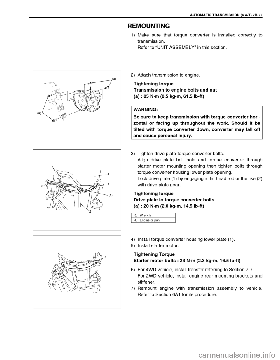
2) Attach transmission to engine.
Tightening torque
Transmission to engine bolts and nut
(a) : 85 N·m (8.5 kg-m, 61.5 lb-ft)
3) Tighten drive plate-torque converter bolts.
Align drive plate bolt hole and torque converter through
starter motor mounting opening then tighten bolts through
torque converter housing lower plate opening.
Lock drive plate (1) by engaging a flat head rod or the like (2)
with drive plate gear.
Tightening torque
Drive plate to torque converter bolts
(a) : 20 N·m (2.0 kg-m, 14.5 lb-ft)
4) Install torque converter housing lower plate (1).
5) Install starter motor.
Tightening Torque
Starter motor bolts : 23 N·m (2.3 kg-m, 16.5 lb-ft)
6) For 4WD vehicle, install transfer referring to Section 7D.
For 2WD vehicle, install engine rear mounting brackets and
stiffener.
7) Remount engine with transmission assembly to vehicle.
Refer to Section 6A1 for its procedure. WARNING:
Be sure to keep transmission with torque converter hori-
zontal or facing up throughout the work. Should it be
tilted with torque converter down, converter may fall off
and cause personal injury.
3. Wrench
4. Engine oil pan
Page 120 of 447
7B-78 AUTOMATIC TRANSMISSION (4 A/T)
UNIT DISASSEMBLY
1) Remove torque converter (1).
2) Remove engine mounting LH bracket.
3) Remove oil cooler (1) and battery ground cable (2) (if still
attached). CAUTION:
Thoroughly clean transmission exterior before over-
hauling it.
Keep working table, tools and hands clean while over-
hauling.
Use special care to handle aluminum parts so as not to
damage them.
Do not expose removed parts to dust. Keep them
always clean.