2000 SUZUKI SWIFT wheel
[x] Cancel search: wheelPage 2 of 447

7A-2 MANUAL TRANSMISSION
GENERAL DESCRIPTION
CONSTRUCTION AND SERVICING
The transmission provides five forward speeds and one reverse speed by means of three synchronizers and
three shafts-input shaft, countershaft and reverse gear shaft. All forward gears are in constant mesh, and
reverse uses a sliding idler gear arrangement.
The low speed synchronizer is mounted on counter shaft and engaged with counter shaft first gear or second
gear, while the high speed synchronizer is done on input shaft and engaged with input shaft third gear or fourth
gear.
The fifth speed synchronizer on input shaft is engaged with input shaft fifth gear mounted on the input shaft.
The double cone synchronizing mechanism is provided to 2nd gear synchromesh device for high performance
of shifting to 2nd gear.
The countershaft turns the final gear and differential assembly, thereby turning the front drive shafts which are
attached to the front wheels.
4WD model is equipped with transfer assembly on transmission being mated to right side of differential output in
transmission.
For servicing, it is necessary to use genuine sealant or its equivalent on mating surfaces of transmission case
which is made of aluminum. The case fastening bolts must be tightened to specified torque by means of torque
wrench. It is also important that all parts are thoroughly cleaned with cleaning fluid and air dried before reas-
sembling.
Further, care must be taken to adjust preload of counter shaft taper roller bearings. New synchronizer rings are
prohibited from being lapped with respective gear cones by using lapping compound before they are assembled.
Page 6 of 447
7A-6 MANUAL TRANSMISSION
OIL CHANGE
1) Before changing or inspecting oil, be sure to stop engine and
lift vehicle horizontally.
2) With vehicle lifted up, check oil level and leakage.
If leakage exists, correct it.
3) Drain old oil and fill new specified oil by specified amount (up
to level hole).
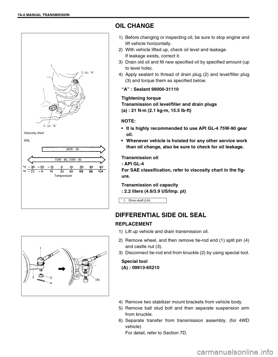
4) Apply sealant to thread of drain plug (2) and level/filler plug
(3) and torque them as specified below.
“A” : Sealant 99000-31110
Tightening torque
Transmission oil level/filler and drain plugs
(a) : 21 N·m (2.1 kg-m, 15.5 lb-ft)
Transmission oil
: API GL-4
For SAE classification, refer to viscosity chart in the fig-
ure.
Transmission oil capacity
: 2.2 liters (4.6/3.9 US/lmp. pt)
DIFFERENTIAL SIDE OIL SEAL
REPLACEMENT
1) Lift up vehicle and drain transmission oil.
2) Remove wheel, and then remove tie-rod end (1) split pin (4)
and castle nut (3).
3) Disconnect tie-rod end from knuckle (2) by using special tool.
Special tool
(A) : 09913-65210
4) Remove two stabilizer mount brackets from vehicle body.
5) Remove ball stud bolt and then separate suspension arm
from knuckle.
6) Separate transfer from transmission assembly. (for 4WD
vehicle)
For detail, refer to Section 7D. NOTE:
It is highly recommended to use API GL-4 75W-90 gear
oil.
Whenever vehicle is hoisted for any other service work
than oil change, also be sure to check for oil leakage.
1. Drive shaft (LH)
Page 62 of 447
7B-20 AUTOMATIC TRANSMISSION (4 A/T)
STALL TEST
This test is to check overall performance of automatic transmis-
sion and engine by measuring stall speed at “D” and “R” ranges.
Be sure to perform this test only when transmission fluid is at nor-
mal operating temperature and its level is between FULL and
LOW marks.
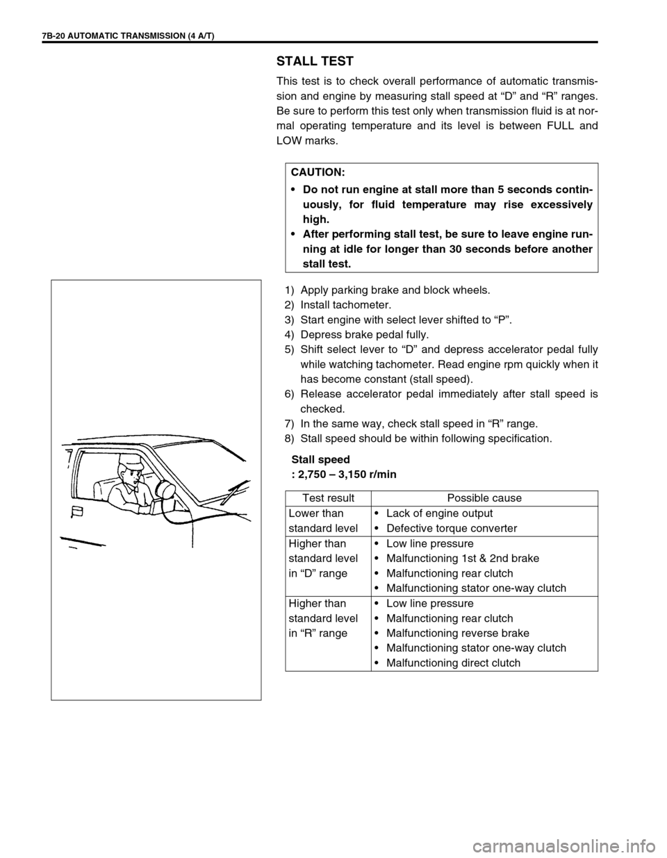
1) Apply parking brake and block wheels.
2) Install tachometer.
3) Start engine with select lever shifted to “P”.
4) Depress brake pedal fully.
5) Shift select lever to “D” and depress accelerator pedal fully
while watching tachometer. Read engine rpm quickly when it
has become constant (stall speed).
6) Release accelerator pedal immediately after stall speed is
checked.
7) In the same way, check stall speed in “R” range.
8) Stall speed should be within following specification.
Stall speed
: 2,750 – 3,150 r/min CAUTION:
Do not run engine at stall more than 5 seconds contin-
uously, for fluid temperature may rise excessively
high.
After performing stall test, be sure to leave engine run-
ning at idle for longer than 30 seconds before another
stall test.
Test result Possible cause
Lower than
standard levelLack of engine output
Defective torque converter
Higher than
standard level
in “D” rangeLow line pressure
Malfunctioning 1st & 2nd brake
Malfunctioning rear clutch
Malfunctioning stator one-way clutch
Higher than
standard level
in “R” rangeLow line pressure
Malfunctioning rear clutch
Malfunctioning reverse brake
Malfunctioning stator one-way clutch
Malfunctioning direct clutch
Page 63 of 447

AUTOMATIC TRANSMISSION (4 A/T) 7B-21
TIME LAG TEST
This test is to check conditions of clutch, reverse brake and fluid
pressure. “Time lag” means time elapsed since select lever is
shifted with engine idling till shock is felt.
1) With chocks placed in front and behind front and rear wheels
respectively, depress brake pedal.
2) Start engine.
3) With stop watch ready, shift select lever from “N” to “D”
range and measure time from that moment till shock is felt.
4) Similarly measure time lag by shifting select lever from “N” to
“R” range.
Specification for time lag
“N”
→
→ → → “D” : Less than 1.0 sec.
“N”
→
→→ → “R” : Less than 1.2 sec.
NOTE:
Make sure that selector cable is properly adjusted.
When repeating this test, be sure to wait at least
minute after select lever is shifted back to “N” range.
Engine should be warmed up fully for this test.
Test result Possible cause
When “N” →
“D”
time lag exceeds specification.Low line pressure
Worn rear clutch
Worn 1st & 2nd brake
When “N” →
“R”
time lag exceeds specification.Low line pressure
Worn rear clutch
Worn direct clutch
Worn reverse brake
Page 64 of 447
7B-22 AUTOMATIC TRANSMISSION (4 A/T)
LINE PRESSURE TEST
Purpose of this test is to check operating conditions of each part
by measuring fluid pressure in fluid pressure line.
Line pressure test requires following conditions.
Automatic fluid is at normal operating temperature (70 –
80°C /158 – 176°F).
Fluid is filled to proper level (between FULL and LOW on
dipstick).
1) Apply parking brake securely and place chocks against
wheels.
2) Remove fluid pressure check hole plug bolt.
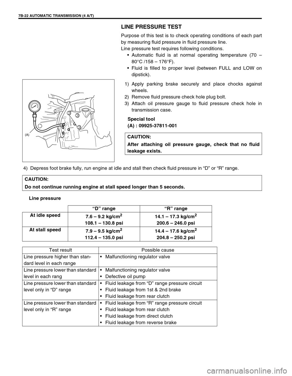
3) Attach oil pressure gauge to fluid pressure check hole in
transmission case.
Special tool
(A) : 09925-37811-001
4) Depress foot brake fully, run engine at idle and stall then check fluid pressure in “D” or “R” range.
Line pressureCAUTION:
After attaching oil pressure gauge, check that no fluid
leakage exists.
(A)
CAUTION:
Do not continue running engine at stall speed longer than 5 seconds.
“D” range “R” range
At idle speed
7.6 – 9.2 kg/cm
2
108.1 – 130.8 psi14.1 – 17.3 kg/cm
2
200.6 – 246.0 psi
At stall speed
7.9 – 9.5 kg/cm
2
112.4 – 135.0 psi14.4 – 17.6 kg/cm
2
204.8 – 250.2 psi
Test result Possible cause
Line pressure higher than stan-
dard level in each rangeMalfunctioning regulator valve
Line pressure lower than standard
level in each rangMalfunctioning regulator valve
Defective oil pump
Line pressure lower than standard
level only in “D” rangeFluid leakage from “D” range pressure circuit
Fluid leakage from 1st & 2nd brake
Fluid leakage from rear clutch
Line pressure lower than standard
level only in “R” rangeFluid leakage from “R” range pressure circuit
Fluid leakage from rear clutch
Fluid leakage from direct clutch
Fluid leakage from reverse brake
Page 97 of 447
AUTOMATIC TRANSMISSION (4 A/T) 7B-55
ON-VEHICLE SERVICE
MAINTENANCE SERVICE
FLUID LEVEL AT NORMAL OPERATING TEMPERA-
TURE
INSPECTION
1) Stop vehicle and place it level.
2) Apply parking brake and place chocks against wheels.
3) With selector at P position, start engine.
4) Warm up engine till fluid temperature reaches normal oper-
ating temperature (70 – 80°C/158 – 176°F). As a guide to
check fluid temperature, warm up engine to normal operat-
ing temperature.
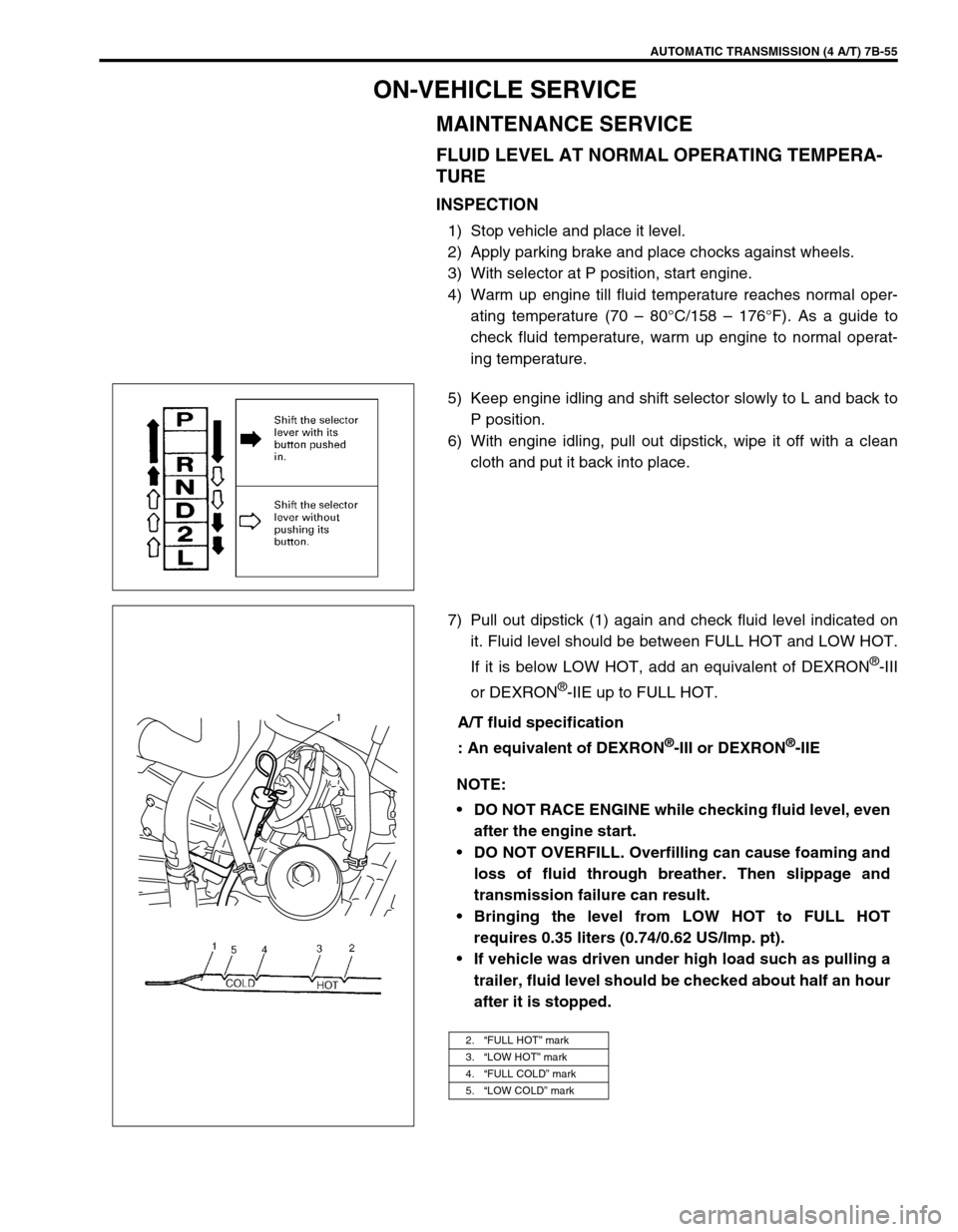
5) Keep engine idling and shift selector slowly to L and back to
P position.
6) With engine idling, pull out dipstick, wipe it off with a clean
cloth and put it back into place.
7) Pull out dipstick (1) again and check fluid level indicated on
it. Fluid level should be between FULL HOT and LOW HOT.
If it is below LOW HOT, add an equivalent of DEXRON
®-III
or DEXRON
®-IIE up to FULL HOT.
A/T fluid specification
: An equivalent of DEXRON
®-III or DEXRON®-IIE
NOTE:
DO NOT RACE ENGINE while checking fluid level, even
after the engine start.
DO NOT OVERFILL. Overfilling can cause foaming and
loss of fluid through breather. Then slippage and
transmission failure can result.
Bringing the level from LOW HOT to FULL HOT
requires 0.35 liters (0.74/0.62 US/Imp. pt).
If vehicle was driven under high load such as pulling a
trailer, fluid level should be checked about half an hour
after it is stopped.
2.“FULL HOT” mark
3.“LOW HOT” mark
4.“FULL COLD” mark
5.“LOW COLD” mark
1
Page 100 of 447

7B-58 AUTOMATIC TRANSMISSION (4 A/T)
INSPECTION
Check selector lever for smooth and clear cut movement and
position indicator for correct indication.
For operation of selector lever, refer to the figure.
TRANSMISSION RANGE SENSOR (SHIFT
SWITCH)
REMOVAL
1) Block wheels and turn select lever to “N” range.
2) Disconnect transmission range sensor coupler and select
cable.
3) Remove transmission range sensor from transmission case.
INSPECTION
1) Disconnect transmission range sensor coupler (2).
2) Check that continuity exists at terminals shown below by
moving selector lever.
CAUTION:
Do not overhaul transmission range sensor.
1. Transmission range sensor
Terminal
Sensor
Position
P
R
N
D
2
LBAHCEDG I F
Page 183 of 447
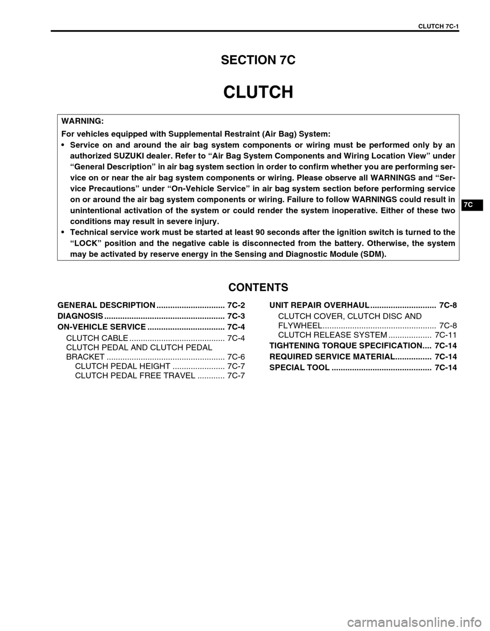
CLUTCH 7C-1
6F1
6F2
6G
6H
6K
7A1
7B1
7C1
7D
7E
7C
8A
8B
8C
8D
8E
9
10
10A
10B
SECTION 7C
CLUTCH
CONTENTS
GENERAL DESCRIPTION .............................. 7C-2
DIAGNOSIS ..................................................... 7C-3
ON-VEHICLE SERVICE .................................. 7C-4
CLUTCH CABLE .......................................... 7C-4
CLUTCH PEDAL AND CLUTCH PEDAL
BRACKET .................................................... 7C-6
CLUTCH PEDAL HEIGHT ....................... 7C-7
CLUTCH PEDAL FREE TRAVEL ............ 7C-7UNIT REPAIR OVERHAUL ............................. 7C-8
CLUTCH COVER, CLUTCH DISC AND
FLYWHEEL.................................................. 7C-8
CLUTCH RELEASE SYSTEM ................... 7C-11
TIGHTENING TORQUE SPECIFICATION.... 7C-14
REQUIRED SERVICE MATERIAL................ 7C-14
SPECIAL TOOL ............................................ 7C-14
WARNING:
For vehicles equipped with Supplemental Restraint (Air Bag) System:
Service on and around the air bag system components or wiring must be performed only by an
authorized SUZUKI dealer. Refer to “Air Bag System Components and Wiring Location View” under
“General Description” in air bag system section in order to confirm whether you are performing ser-
vice on or near the air bag system components or wiring. Please observe all WARNINGS and “Ser-
vice Precautions” under “On-Vehicle Service” in air bag system section before performing service
on or around the air bag system components or wiring. Failure to follow WARNINGS could result in
unintentional activation of the system or could render the system inoperative. Either of these two
conditions may result in severe injury.
Technical service work must be started at least 90 seconds after the ignition switch is turned to the
“LOCK” position and the negative cable is disconnected from the battery. Otherwise, the system
may be activated by reserve energy in the Sensing and Diagnostic Module (SDM).