Page 129 of 447
AUTOMATIC TRANSMISSION (4 A/T) 7B-87
INSPECTION
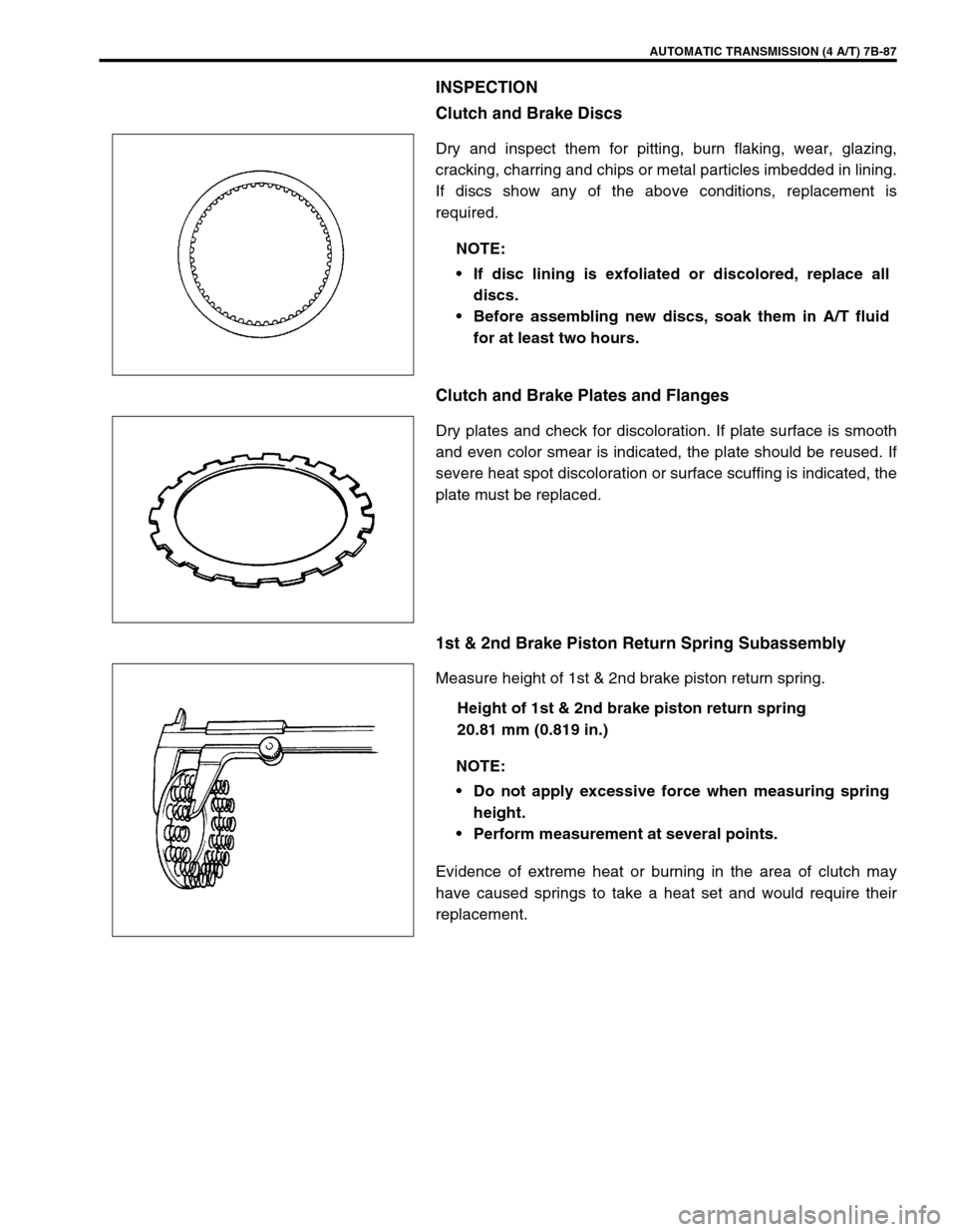
Clutch and Brake Discs
Dry and inspect them for pitting, burn flaking, wear, glazing,
cracking, charring and chips or metal particles imbedded in lining.
If discs show any of the above conditions, replacement is
required.
Clutch and Brake Plates and Flanges
Dry plates and check for discoloration. If plate surface is smooth
and even color smear is indicated, the plate should be reused. If
severe heat spot discoloration or surface scuffing is indicated, the
plate must be replaced.
1st & 2nd Brake Piston Return Spring Subassembly
Measure height of 1st & 2nd brake piston return spring.
Height of 1st & 2nd brake piston return spring
20.81 mm (0.819 in.)
Evidence of extreme heat or burning in the area of clutch may
have caused springs to take a heat set and would require their
replacement.NOTE:
If disc lining is exfoliated or discolored, replace all
discs.
Before assembling new discs, soak them in A/T fluid
for at least two hours.
NOTE:
Do not apply excessive force when measuring spring
height.
Perform measurement at several points.
Page 134 of 447
7B-92 AUTOMATIC TRANSMISSION (4 A/T)
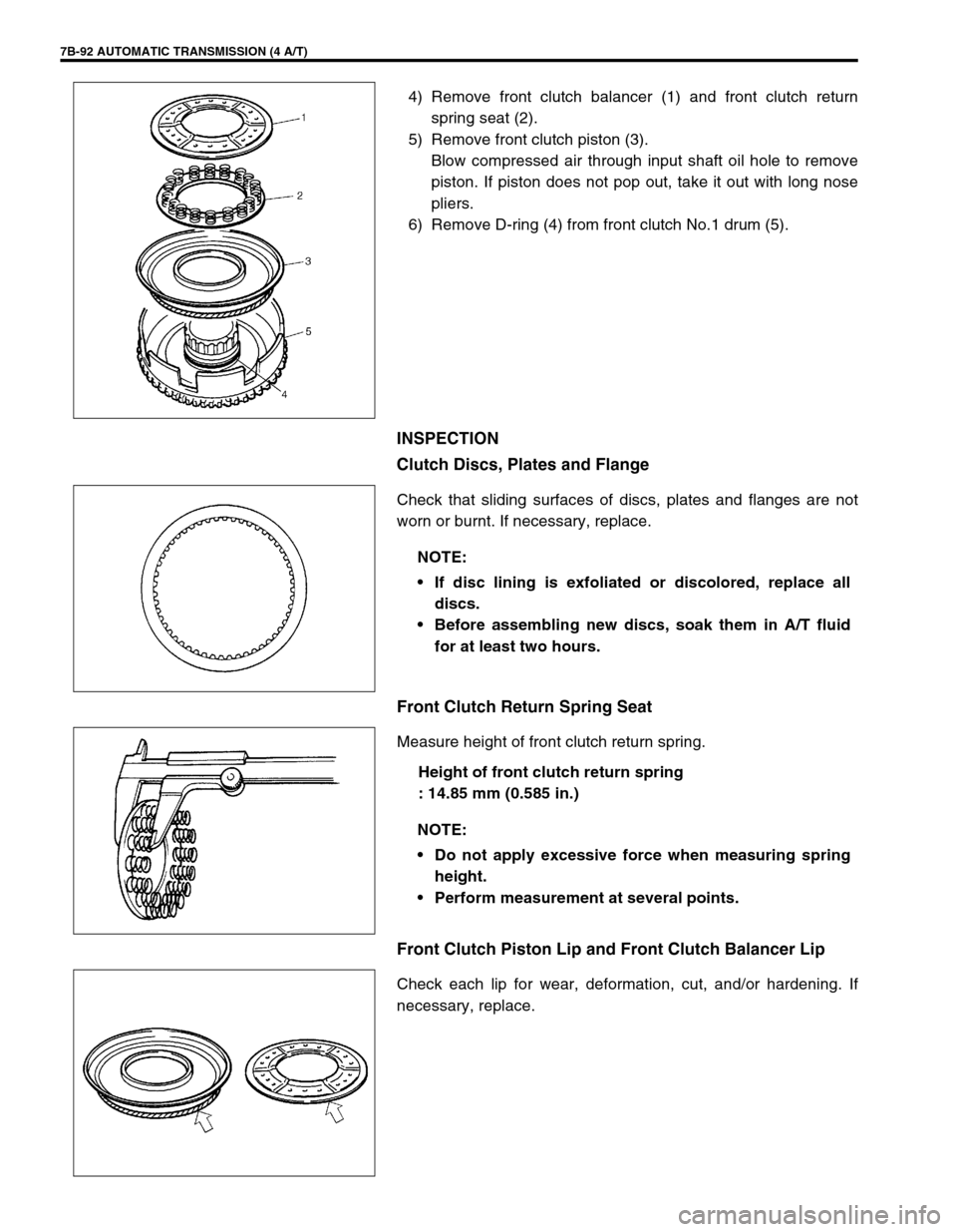
4) Remove front clutch balancer (1) and front clutch return
spring seat (2).
5) Remove front clutch piston (3).
Blow compressed air through input shaft oil hole to remove
piston. If piston does not pop out, take it out with long nose
pliers.
6) Remove D-ring (4) from front clutch No.1 drum (5).
INSPECTION
Clutch Discs, Plates and Flange
Check that sliding surfaces of discs, plates and flanges are not
worn or burnt. If necessary, replace.
Front Clutch Return Spring Seat
Measure height of front clutch return spring.
Height of front clutch return spring
: 14.85 mm (0.585 in.)
Front Clutch Piston Lip and Front Clutch Balancer Lip
Check each lip for wear, deformation, cut, and/or hardening. If
necessary, replace.
NOTE:
If disc lining is exfoliated or discolored, replace all
discs.
Before assembling new discs, soak them in A/T fluid
for at least two hours.
NOTE:
Do not apply excessive force when measuring spring
height.
Perform measurement at several points.
Page 139 of 447
AUTOMATIC TRANSMISSION (4 A/T) 7B-97
Rear Clutch Return Spring Seat
Measure height of overdrive clutch return spring.
Height of overdrive clutch return spring
: 22.01 mm (0.867 in.)
ASSEMBLY
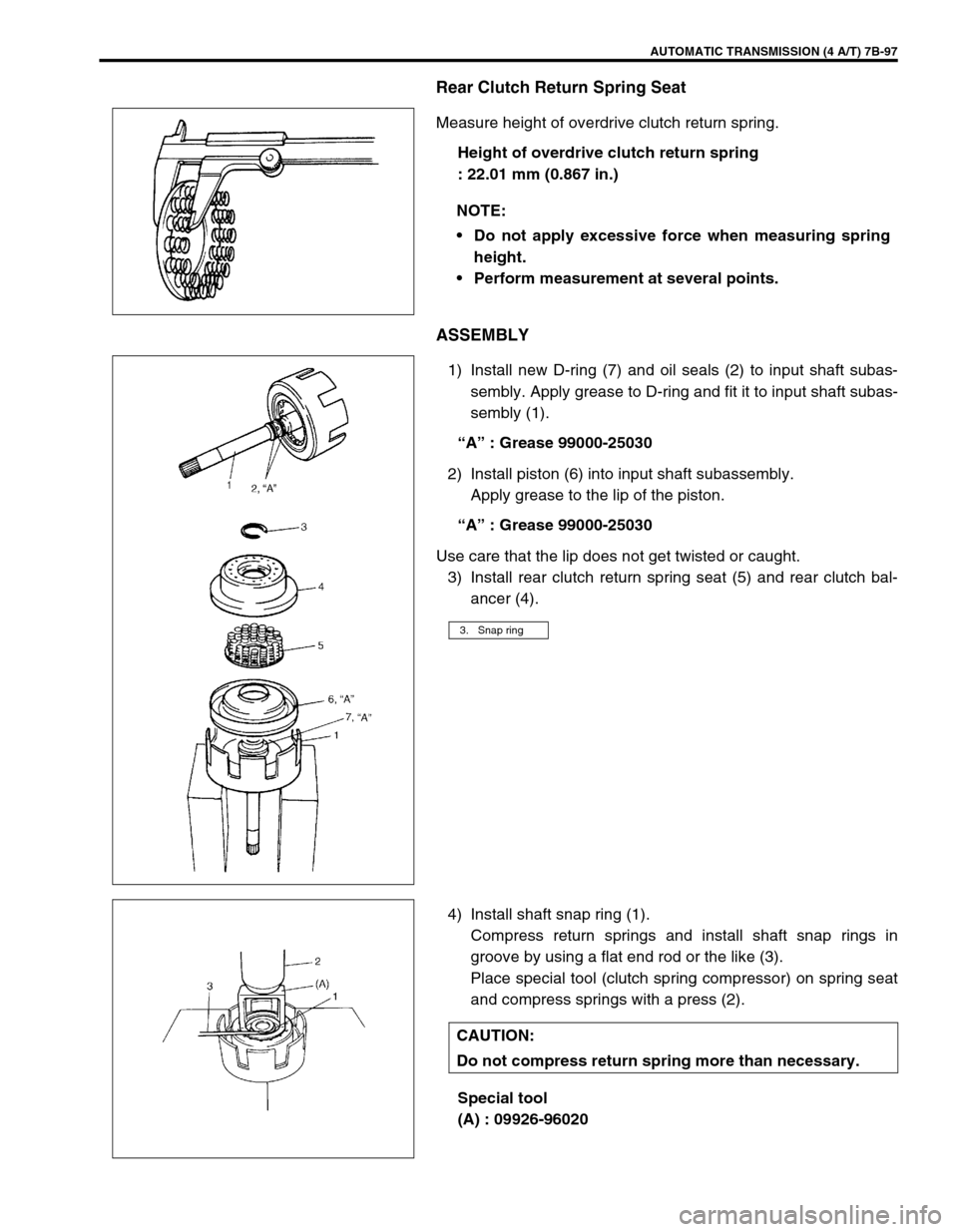
1) Install new D-ring (7) and oil seals (2) to input shaft subas-
sembly. Apply grease to D-ring and fit it to input shaft subas-
sembly (1).
“A” : Grease 99000-25030
2) Install piston (6) into input shaft subassembly.
Apply grease to the lip of the piston.
“A” : Grease 99000-25030
Use care that the lip does not get twisted or caught.
3) Install rear clutch return spring seat (5) and rear clutch bal-
ancer (4).
4) Install shaft snap ring (1).
Compress return springs and install shaft snap rings in
groove by using a flat end rod or the like (3).
Place special tool (clutch spring compressor) on spring seat
and compress springs with a press (2).
Special tool
(A) : 09926-96020 NOTE:
Do not apply excessive force when measuring spring
height.
Perform measurement at several points.
3. Snap ring
CAUTION:
Do not compress return spring more than necessary.
Page 143 of 447
AUTOMATIC TRANSMISSION (4 A/T) 7B-101
4) Remove direct clutch balancer (1) and direct clutch return
spring seat (2).
5) Remove direct clutch piston (3).
Blow compressed air through input shaft oil hole to remove
piston. If piston does not pop out, take it out with long nose
pliers.
6) Remove D-ring (4) from direct clutch No.1 drum (5).
INSPECTION
Clutch Discs, Plates and Flange
Check that sliding surfaces of discs, plates and flanges are not
worn or burnt. If necessary, replace.
Direct Clutch Return Spring Seat
Measure height of direct clutch return spring.
Height of direct clutch return spring
: 16.3 mm (0.642 in.)
.
NOTE:
If disc lining is exfoliated or discolored, replace all
discs.
Before assembling new discs, soak them in A/T fluid
for at least two hours.
NOTE:
Do not apply excessive force when measuring spring
height.
Perform measurement at several points.
Page 183 of 447
CLUTCH 7C-1
6F1
6F2
6G
6H
6K
7A1
7B1
7C1
7D
7E
7C
8A
8B
8C
8D
8E
9
10
10A
10B
SECTION 7C
CLUTCH
CONTENTS
GENERAL DESCRIPTION .............................. 7C-2
DIAGNOSIS ..................................................... 7C-3
ON-VEHICLE SERVICE .................................. 7C-4
CLUTCH CABLE .......................................... 7C-4
CLUTCH PEDAL AND CLUTCH PEDAL
BRACKET .................................................... 7C-6
CLUTCH PEDAL HEIGHT ....................... 7C-7
CLUTCH PEDAL FREE TRAVEL ............ 7C-7UNIT REPAIR OVERHAUL ............................. 7C-8
CLUTCH COVER, CLUTCH DISC AND
FLYWHEEL.................................................. 7C-8
CLUTCH RELEASE SYSTEM ................... 7C-11
TIGHTENING TORQUE SPECIFICATION.... 7C-14
REQUIRED SERVICE MATERIAL................ 7C-14
SPECIAL TOOL ............................................ 7C-14
WARNING:
For vehicles equipped with Supplemental Restraint (Air Bag) System:
Service on and around the air bag system components or wiring must be performed only by an
authorized SUZUKI dealer. Refer to “Air Bag System Components and Wiring Location View” under
“General Description” in air bag system section in order to confirm whether you are performing ser-
vice on or near the air bag system components or wiring. Please observe all WARNINGS and “Ser-
vice Precautions” under “On-Vehicle Service” in air bag system section before performing service
on or around the air bag system components or wiring. Failure to follow WARNINGS could result in
unintentional activation of the system or could render the system inoperative. Either of these two
conditions may result in severe injury.
Technical service work must be started at least 90 seconds after the ignition switch is turned to the
“LOCK” position and the negative cable is disconnected from the battery. Otherwise, the system
may be activated by reserve energy in the Sensing and Diagnostic Module (SDM).
Page 189 of 447
CLUTCH 7C-7
CLUTCH PEDAL HEIGHT
Adjust clutch pedal (1) height with adjusting bolt (2) located on
pedal bracket (3) so that clutch pedal height is same as brake
pedal (4) height.
Height difference
“a” : 0 mm (0 in.)
CLUTCH PEDAL FREE TRAVEL
1) Confirm that clutch pedal height is specification.
2) Depress clutch pedal (1), stop the moment clutch resistance
is felt, and measure distance (clutch pedal free travel). Free
travel should be within the following specification.
Pedal free travel
“b” : 15 – 20 mm (0.6 – 0.8 in.)
3) If free travel is out of specification, adjust it with cable joint
nut (1).
Release lever free travel (Reference)
“c” : 0 – 2 mm (0 – 0.08 in.)
4) After checking clutch pedal free travel, also check clutch for
proper function with engine running.
Page 210 of 447
7D-12 TRANSFER
TRANSFER OUTPUT RETAINER
ADJUSTMENT
Special tool
(A) : 09922-76140
(B) : 09922-76150
(C) : 09922-76340
(D) : 09922-76430
“a”: Pinion dummy (special tool) height 1. Transfer output retainer
“b”: Height from retainer installation face to pinion dummy 2. Left case
“c”: Distance from retainer installation face to end face of bearing race (“b” – “a”) 3. Pinion shaft bearing
“d”: Distance from end face of left case to cylinder section of reduction driven gear 4. Reduction driven gear
“e”: Outer diameter of cylinder section of reduction driven gear (29.7 mm/1.1693 in.) 5. Bevel pinion shaft
“f”: Distance from end face of left case to center shaft of reduction driven gear (“d” + “e”/2)
“g”: Dimension marked on bevel pinion shaft (Marked in shaft in mm)
“h”: Shim size for mounting distance adjustment (“g” + “c” – “f”)
Page 211 of 447
TRANSFER 7D-13
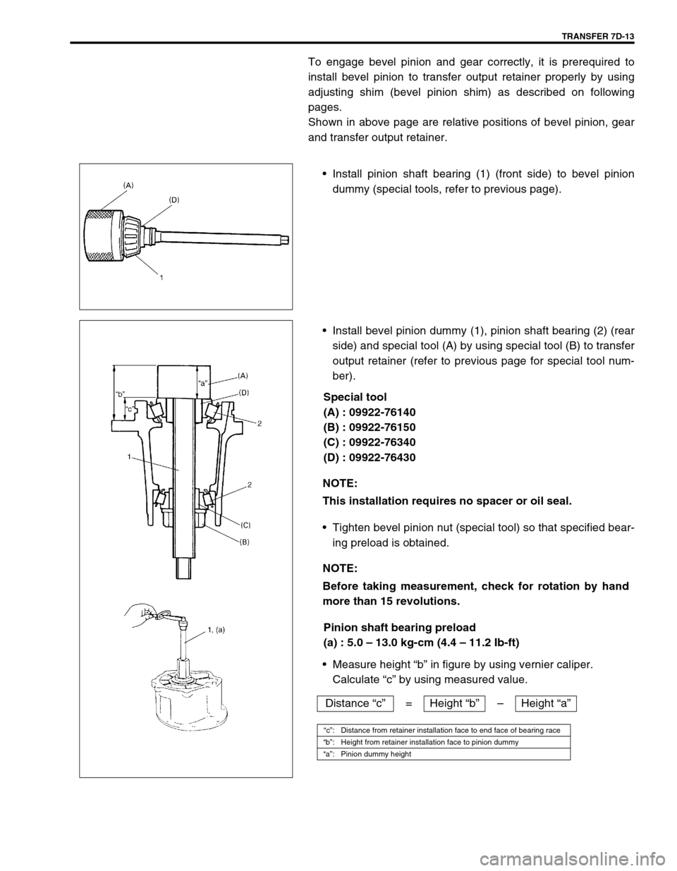
To engage bevel pinion and gear correctly, it is prerequired to
install bevel pinion to transfer output retainer properly by using
adjusting shim (bevel pinion shim) as described on following
pages.
Shown in above page are relative positions of bevel pinion, gear
and transfer output retainer.
Install pinion shaft bearing (1) (front side) to bevel pinion
dummy (special tools, refer to previous page).
Install bevel pinion dummy (1), pinion shaft bearing (2) (rear
side) and special tool (A) by using special tool (B) to transfer
output retainer (refer to previous page for special tool num-
ber).
Special tool
(A) : 09922-76140
(B) : 09922-76150
(C) : 09922-76340
(D) : 09922-76430
Tighten bevel pinion nut (special tool) so that specified bear-
ing preload is obtained.
Pinion shaft bearing preload
(a) : 5.0 – 13.0 kg-cm (4.4 – 11.2 Ib-ft)
Measure height “b” in figure by using vernier caliper.
Calculate “c” by using measured value.
NOTE:
This installation requires no spacer or oil seal.
NOTE:
Before taking measurement, check for rotation by hand
more than 15 revolutions.
Distance “c”= Height “b”–Height “a”
“c”: Distance from retainer installation face to end face of bearing race
“b”: Height from retainer installation face to pinion dummy
“a”: Pinion dummy height