Page 216 of 447

7D-18 TRANSFER
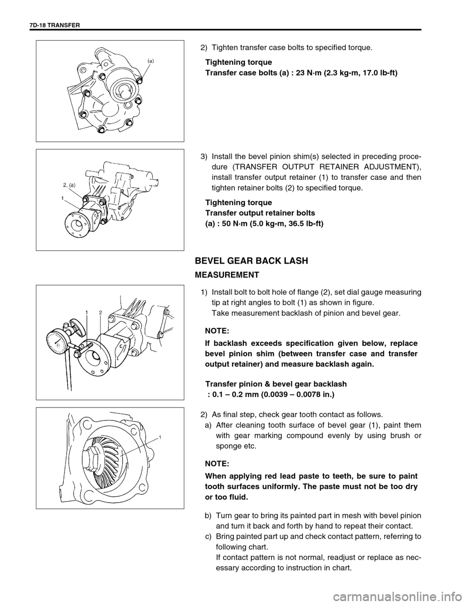
2) Tighten transfer case bolts to specified torque.
Tightening torque
Transfer case bolts (a) : 23 N·m (2.3 kg-m, 17.0 lb-ft)
3) Install the bevel pinion shim(s) selected in preceding proce-
dure (TRANSFER OUTPUT RETAINER ADJUSTMENT),
install transfer output retainer (1) to transfer case and then
tighten retainer bolts (2) to specified torque.
Tightening torque
Transfer output retainer bolts
(a) : 50 N·m (5.0 kg-m, 36.5 lb-ft)
BEVEL GEAR BACK LASH
MEASUREMENT
1) Install bolt to bolt hole of flange (2), set dial gauge measuring
tip at right angles to bolt (1) as shown in figure.
Take measurement backlash of pinion and bevel gear.
Transfer pinion & bevel gear backlash
: 0.1 – 0.2 mm (0.0039 – 0.0078 in.)
2) As final step, check gear tooth contact as follows.
a) After cleaning tooth surface of bevel gear (1), paint them
with gear marking compound evenly by using brush or
sponge etc.
b) Turn gear to bring its painted part in mesh with bevel pinion
and turn it back and forth by hand to repeat their contact.
c) Bring painted part up and check contact pattern, referring to
following chart.
If contact pattern is not normal, readjust or replace as nec-
essary according to instruction in chart.
NOTE:
If backlash exceeds specification given below, replace
bevel pinion shim (between transfer case and transfer
output retainer) and measure backlash again.
NOTE:
When applying red lead paste to teeth, be sure to paint
tooth surfaces uniformly. The paste must not be too dry
or too fluid.
Page 218 of 447

7D-20 TRANSFER
UNIT INSTALLATION
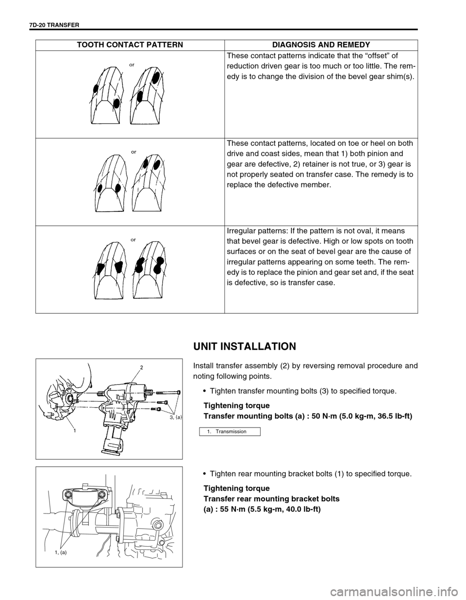
Install transfer assembly (2) by reversing removal procedure and
noting following points.
Tighten transfer mounting bolts (3) to specified torque.
Tightening torque
Transfer mounting bolts (a) : 50 N·m (5.0 kg-m, 36.5 lb-ft)
Tighten rear mounting bracket bolts (1) to specified torque.
Tightening torque
Transfer rear mounting bracket bolts
(a) : 55 N·m (5.5 kg-m, 40.0 lb-ft)These contact patterns indicate that the “offset” of
reduction driven gear is too much or too little. The rem-
edy is to change the division of the bevel gear shim(s).
These contact patterns, located on toe or heel on both
drive and coast sides, mean that 1) both pinion and
gear are defective, 2) retainer is not true, or 3) gear is
not properly seated on transfer case. The remedy is to
replace the defective member.
Irregular patterns: If the pattern is not oval, it means
that bevel gear is defective. High or low spots on tooth
surfaces or on the seat of bevel gear are the cause of
irregular patterns appearing on some teeth. The rem-
edy is to replace the pinion and gear set and, if the seat
is defective, so is transfer case. TOOTH CONTACT PATTERN DIAGNOSIS AND REMEDY
1. Transmission
1, (a)
Page 242 of 447

7F-20 REAR DIFFERENTIAL
UNIT ASSEMBLY
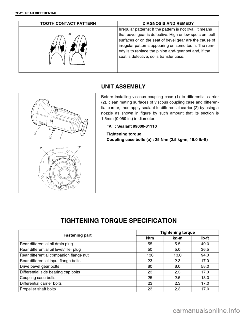
Before installing viscous coupling case (1) to differential carrier
(2), clean mating surfaces of viscous coupling case and differen-
tial carrier, then apply sealant to differential carrier (2) by using a
nozzle as shown in figure by such amount that its section is
1.5mm (0.059 in.) in diameter.
“A” : Sealant 99000-31110
Tightening torque
Coupling case bolts (a) : 25 N·m (2.5 kg-m, 18.0 lb-ft)
TIGHTENING TORQUE SPECIFICATION
Irregular patterns: If the pattern is not oval, it means
that bevel gear is defective. High or low spots on tooth
surfaces or on the seat of bevel gear are the cause of
irregular patterns appearing on some teeth. The rem-
edy is to replace the pinion and-gear set and, if the
seat is defective, so is transfer case. TOOTH CONTACT PATTERN DIAGNOSIS AND REMEDY
Fastening partTightening torque
Nm kg-m lb-ft
Rear differential oil drain plug 55 5.5 40.0
Rear differential oil level/filler plug 50 5.0 36.5
Rear differential companion flange nut 130 13.0 94.0
Rear differential input flange bolts 23 2.3 17.0
Drive bevel gear bolts 80 8.0 58.0
Differential side bearing cap bolts 23 2.3 17.0
Coupling case bolts 25 2.5 18.0
Differential carrier bolts 23 2.3 17.0
Propeller shaft bolts 23 2.3 17.0