2000 SUZUKI SWIFT check engine light
[x] Cancel search: check engine lightPage 58 of 447

7B-16 AUTOMATIC TRANSMISSION (4 A/T)
2. DIAGNOSTIC TROUBLE CODE (DTC) CHECK, RECORD AND CLEARANCE
To check DTC, refer to “DTC CHECK” in this section. When a DTC exists, it means existence of a malfunction in
the system represented by that code but whether it still exists (current) or it occurred in the past and has gone
(history) is unknown. To know it, clear this DTC once (Refer to “DTC CLEARANCE” in this section.), perform
test drive and/or “TROUBLE SYMPTOM CONFIRMATION” in this section and then check DTC again as
described in “DTC CHECK”. Attempt to diagnose the trouble based on the DTC recorded in this step only or fail-
ure to clear the DTC in this step may mislead the diagnosis or make diagnosing difficult. Even after checking the
DTC with the SUZUKI scan tool, diagnosis should be performed according to this flow chart to check TCM for
proper self-diagnosis function.
3 and 4. VISUAL INSPECTION
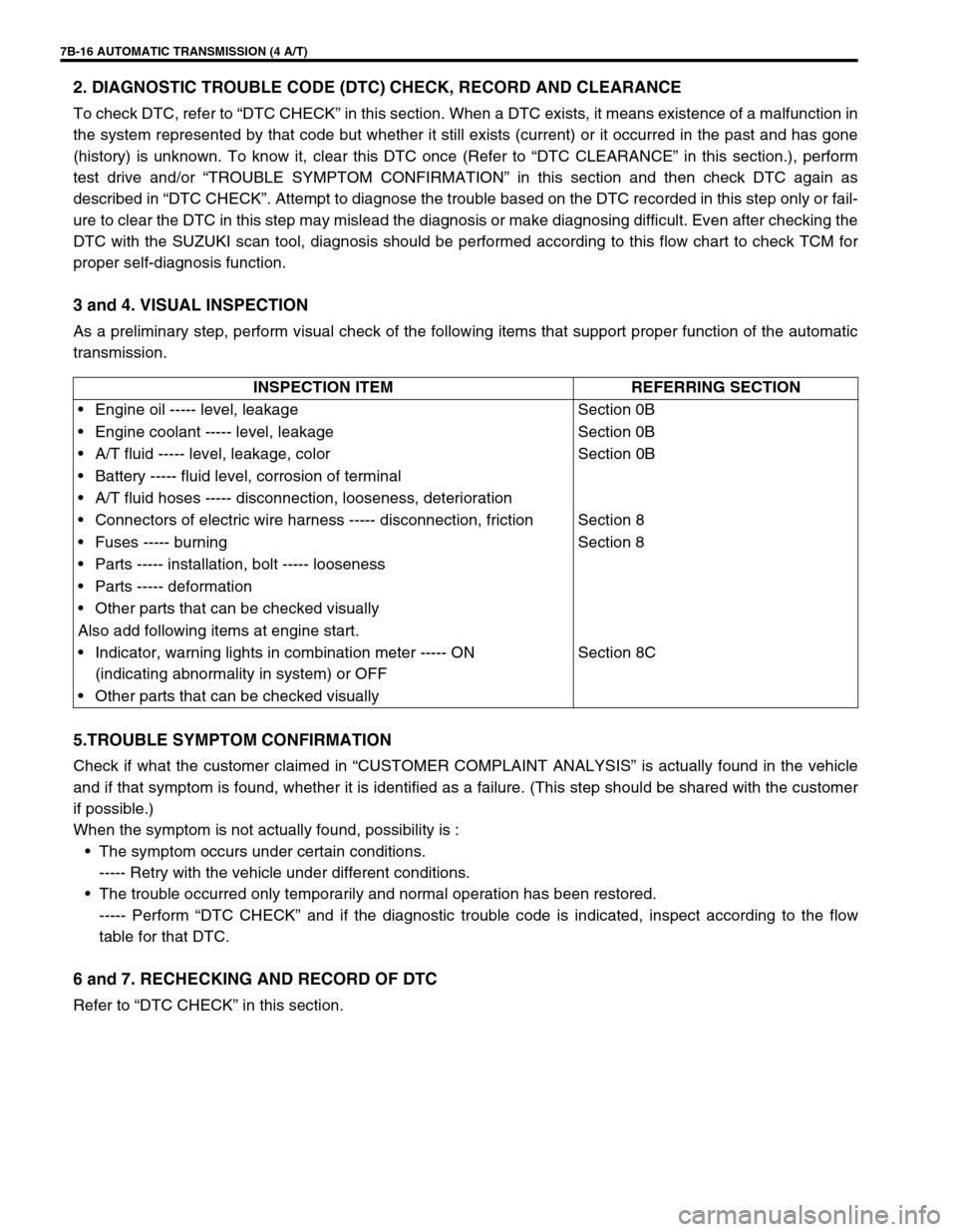
As a preliminary step, perform visual check of the following items that support proper function of the automatic
transmission.
5.TROUBLE SYMPTOM CONFIRMATION
Check if what the customer claimed in “CUSTOMER COMPLAINT ANALYSIS” is actually found in the vehicle
and if that symptom is found, whether it is identified as a failure. (This step should be shared with the customer
if possible.)
When the symptom is not actually found, possibility is :
The symptom occurs under certain conditions.
----- Retry with the vehicle under different conditions.
The trouble occurred only temporarily and normal operation has been restored.
----- Perform “DTC CHECK” and if the diagnostic trouble code is indicated, inspect according to the flow
table for that DTC.
6 and 7. RECHECKING AND RECORD OF DTC
Refer to “DTC CHECK” in this section.INSPECTION ITEM REFERRING SECTION
Engine oil ----- level, leakage Section 0B
Engine coolant ----- level, leakage Section 0B
A/T fluid ----- level, leakage, color Section 0B
Battery ----- fluid level, corrosion of terminal
A/T fluid hoses ----- disconnection, looseness, deterioration
Connectors of electric wire harness ----- disconnection, friction Section 8
Fuses ----- burning Section 8
Parts ----- installation, bolt ----- looseness
Parts ----- deformation
Other parts that can be checked visually
Also add following items at engine start.
Indicator, warning lights in combination meter ----- ON
(indicating abnormality in system) or OFFSection 8C
Other parts that can be checked visually
Page 112 of 447

7B-70 AUTOMATIC TRANSMISSION (4 A/T)
LEARNING CONTROL INITIALIZATION
When one or more operations such as shown below are per-
formed, all learned contents which are stored in TCM memory
should be erased after the operations.
Replacing transmission with new or used one.
Repairing transmission partially by replacing any brake com-
ponent parts with new and/or used brake disc(s), plate(s)
and/or flange.
Repairing transmission partially by replacing any clutch com-
ponent parts with new and/or used clutch disc(s), plate(s)
and/or flange.
Replacing TCM with used one.
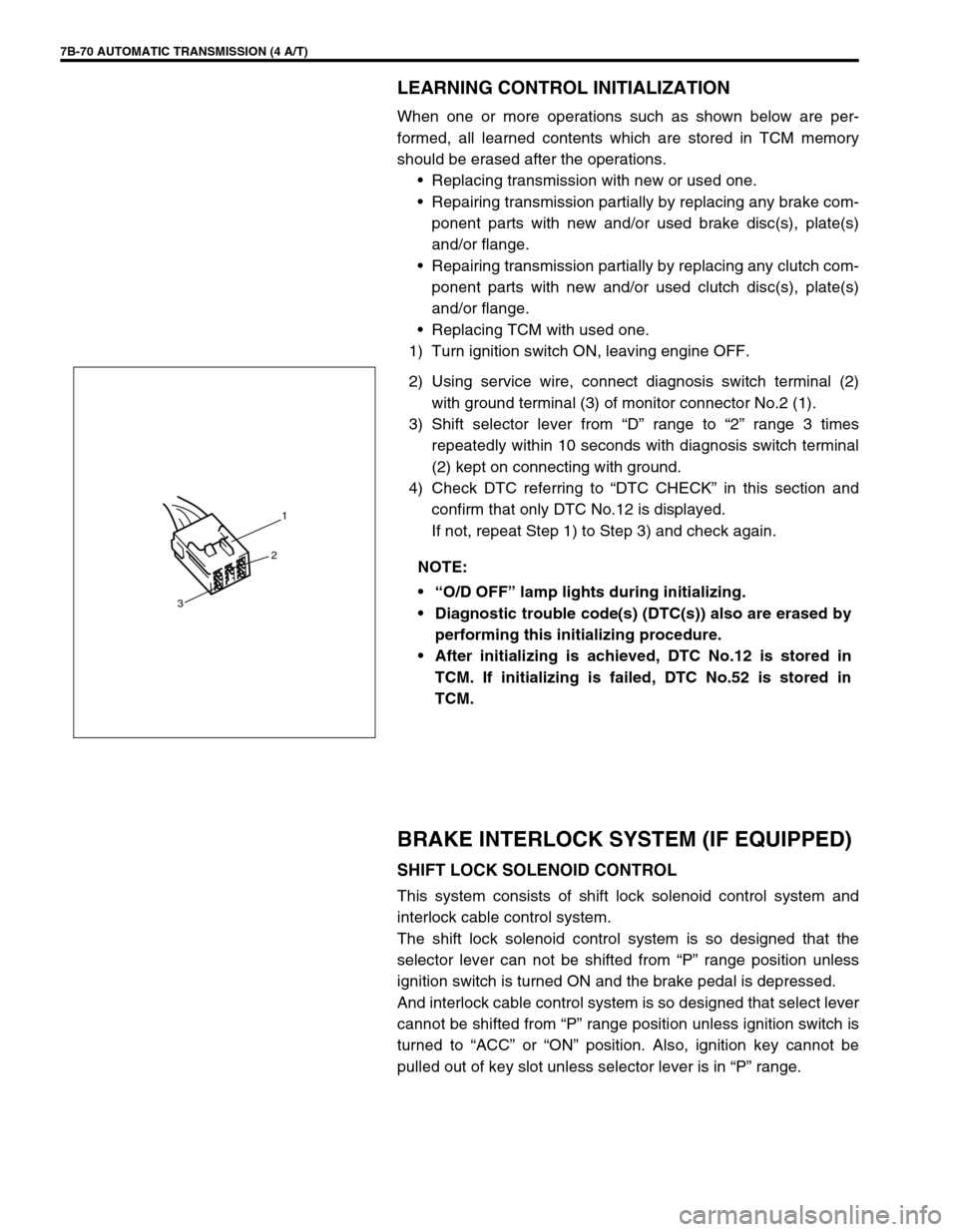
1) Turn ignition switch ON, leaving engine OFF.
2) Using service wire, connect diagnosis switch terminal (2)
with ground terminal (3) of monitor connector No.2 (1).
3) Shift selector lever from “D” range to “2” range 3 times
repeatedly within 10 seconds with diagnosis switch terminal
(2) kept on connecting with ground.
4) Check DTC referring to “DTC CHECK” in this section and
confirm that only DTC No.12 is displayed.
If not, repeat Step 1) to Step 3) and check again.
BRAKE INTERLOCK SYSTEM (IF EQUIPPED)
SHIFT LOCK SOLENOID CONTROL
This system consists of shift lock solenoid control system and
interlock cable control system.
The shift lock solenoid control system is so designed that the
selector lever can not be shifted from “P” range position unless
ignition switch is turned ON and the brake pedal is depressed.
And interlock cable control system is so designed that select lever
cannot be shifted from “P” range position unless ignition switch is
turned to “ACC” or “ON” position. Also, ignition key cannot be
pulled out of key slot unless selector lever is in “P” range. NOTE:
“O/D OFF” lamp lights during initializing.
Diagnostic trouble code(s) (DTC(s)) also are erased by
performing this initializing procedure.
After initializing is achieved, DTC No.12 is stored in
TCM. If initializing is failed, DTC No.52 is stored in
TCM.
1
2
3
Page 249 of 447

BODY ELECTRICAL SYSTEM 8-5
SPEEDOMETER AND VSS
FUEL METER AND FUEL LEVEL SENSOR (GAUGE UNIT)
ENGINE COOLANT TEMPERATURE (ECT) METER AND ECT SENSOR
OIL PRESSURE WARNING LIGHT
Condition Possible Cause Correction
Speedometer shows
no operation or incor-
rect operation“IG/METER” and/or “RADIO/DOME” fuse(s)
blownReplace fuse(s) to check for short.
VSS faulty Check VSS.
Printed plate in combination meter faulty Check printed plate.
Wiring or grounding faulty Repair circuit.
Signal rotor on differential case faulty Check signal rotor.
Speedometer faulty Replace speedometer.
Condition Possible Cause Correction
Fuel meter shows no
operation or incorrect
operation“IG/METER” fuse blown Replace fuse to check for short.
Fuel gauge unit faulty Check fuel gauge unit.
Printed plate in combination meter faulty Check printed plate.
Fuel meter faulty Check fuel meter.
Wiring or grounding faulty Repair circuit.
Condition Possible Cause Correction
Engine coolant temp.
meter shows no oper-
ation or incorrect
operation“IG/METER” fuse blown Replace fuse to check for short.
ECT meter faulty Check ECT meter.
Printed plate in combination meter faulty Check printed plate.
ECT sensor faulty Check ECT sensor.
Wiring or grounding faulty Repair circuit.
Condition Possible Cause Correction
Oil pressure warning
light does not light up
when turn the ignition
switch to ON position
at engine offBulb in combination meter blown Replace bulb.
“IG/METER” fuse blown Replace fuse to check for short.
Printed plate in combination meter faulty Check printed plate.
Oil pressure switch faulty Check oil pressure switch.
Wiring or grounding faulty Repair circuit.
Oil pressure warning
light stay onOil pressure switch faulty Check oil pressure switch.
Page 259 of 447

BODY ELECTRICAL SYSTEM 8-15
COMBINATION METER
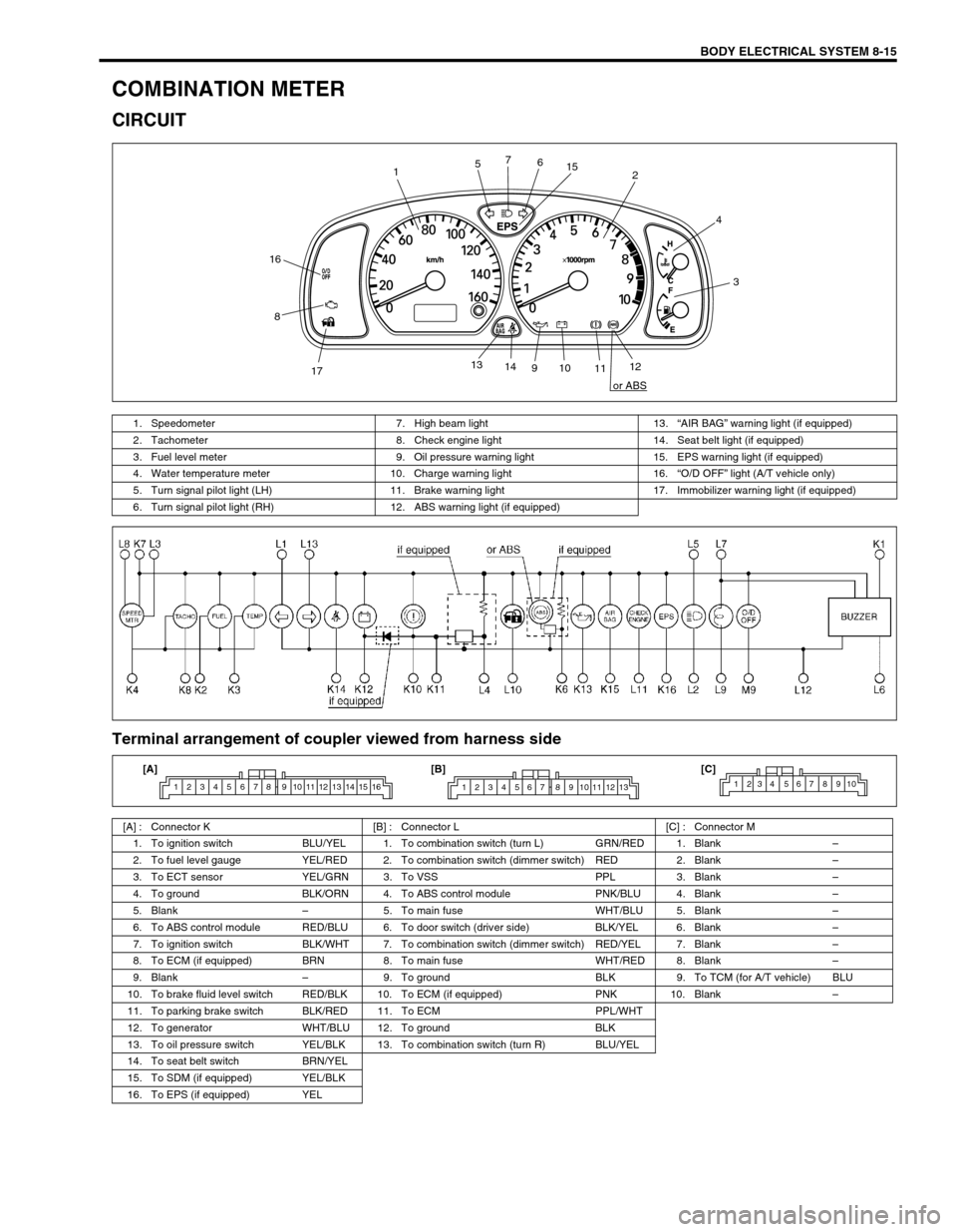
CIRCUIT
Terminal arrangement of coupler viewed from harness side
12
3 4
56 7
8
910
1112 13
14
1715
16
or ABS
1. Speedometer 7. High beam light 13.“AIR BAG” warning light (if equipped)
2. Tachometer 8. Check engine light 14. Seat belt light (if equipped)
3. Fuel level meter 9. Oil pressure warning light 15. EPS warning light (if equipped)
4. Water temperature meter 10. Charge warning light 16.“O/D OFF” light (A/T vehicle only)
5. Turn signal pilot light (LH) 11. Brake warning light 17. Immobilizer warning light (if equipped)
6. Turn signal pilot light (RH) 12. ABS warning light (if equipped)
[A] : Connector K [B] : Connector L [C] : Connector M
1. To ignition switch BLU/YEL 1. To combination switch (turn L) GRN/RED 1. Blank–
2. To fuel level gauge YEL/RED 2. To combination switch (dimmer switch) RED 2. Blank–
3. To ECT sensor YEL/GRN 3. To VSS PPL 3. Blank–
4. To ground BLK/ORN 4. To ABS control module PNK/BLU 4. Blank–
5. Blank–5. To main fuse WHT/BLU 5. Blank–
6. To ABS control module RED/BLU 6. To door switch (driver side) BLK/YEL 6. Blank–
7. To ignition switch BLK/WHT 7. To combination switch (dimmer switch) RED/YEL 7. Blank–
8. To ECM (if equipped) BRN 8. To main fuse WHT/RED 8. Blank–
9. Blank–9. To ground BLK 9. To TCM (for A/T vehicle) BLU
10. To brake fluid level switch RED/BLK 10. To ECM (if equipped) PNK 10. Blank–
11. To parking brake switch BLK/RED 11. To ECM PPL/WHT
12. To generator WHT/BLU 12. To ground BLK
13. To oil pressure switch YEL/BLK 13. To combination switch (turn R) BLU/YEL
14. To seat belt switch BRN/YEL
15. To SDM (if equipped) YEL/BLK
16. To EPS (if equipped) YEL
1 2 3 4 5 6 7 8 9 10 11 12 13 14 15 161 2 3 4 5 6 7 8 9 10 11 12 131234 567 8910[A] [B] [C]
Page 261 of 447

BODY ELECTRICAL SYSTEM 8-17
FUEL LEVEL SENSOR (GAUGE UNIT)
REMOVAL
Remove fuel pump assembly (1) referring to Section 6C.
INSTALLATION
Install fuel pump assembly (1) referring to Section 6C.
INSPECTION
Check that resistance between terminals “a” and “b” of fuel
level sensor changes with change of float position.
Check resistance between terminals “a” and “b” in each float
position below.
If the measured value is out of specification, replace.
Fuel level sensor specification
SPEED METER AND VSS
VSS
REMOVAL AND INSTALLATION
Refer to “VSS” in Section 6E1.
ENGINE COOLANT TEMPERATURE (ECT)
METER AND SENSOR
ENGINE COOLANT TEMPERATURE (ECT) METER
INSPECTION
Operation check
1) Remove combination meter. Refer to “COMBINATION
METER”.
2) Remove “YEL/GRN” wire terminal from combination meter
connector and reconnect combination connectors to combi-
nation meter.
3) Turn ignition switch ON, and check that pointer (2) of ECT
meter indicates “C” as shown in figure.
4) Ignition switch OFF.
5) Short “YEL/GRN” wire terminal to body ground through a 3.4
W bulb (1) as shown in figure.
6) Turn ignition switch ON, and check that bulb light up and
pointer (2) of meter moves from “C” to “H”.
If check result is not satisfied, replace.Float Position Resistance (Ω
)
Full Upper “c”59.6 mm (2.35 in.) 2 - 4
Middle (1/2) “d”121.6 mm (4.79 in.) 29.5 - 35.5
Full Lower “e”202.3 mm (7.96 in.) 119 - 121
“a”“b”
1
“c”
“d”
“e”
YEL/GRNC
H1
2
Page 262 of 447

8-18 BODY ELECTRICAL SYSTEM
ECT SENSOR
REMOVAL, INSTALLATION AND INSPECTION
Refer to “ECT SENSOR” in Section 6E1.
OIL PRESSURE WARNING LIGHT
OIL PRESSURE SWITCH
ON-VEHICLE INSPECTION
1) Disconnect oil pressure switch (1) lead wire.
2) Check for continuity between oil pressure switch terminal (2)
and cylinder block (3) as shown in figure.
If not, replace oil pressure switch (1).
Oil pressure switch specification
During engine running : No continuity
At engine stop : Continuity
REMOVAL AND INSTALLATION
Refer to “OIL PRESSURE CHECK” in Section 6A1.
BRAKE FLUID LEVEL AND PARKING BRAKE
WARNING LIGHT
BRAKE FLUID LEVEL SWITCH
INSPECTION
Check for continuity between terminals of brake fluid level switch
coupler.
If found defective, replace switch.
Brake fluid level switch specification
OFF position (float up) : No continuity
ON position (float down) : Continuity
Page 279 of 447

IMMOBILIZER CONTROL SYSTEM 8G-1
6F1
6F2
6G
6H
6K
7A
7A1
7B1
7C1
7D
7E
7F
8A
8B
8C
8D
8G
9
10
10A
10B
SECTION 8G
IMMOBILIZER CONTROL SYSTEM
CONTENTS
GENERAL DESCRIPTION ............................. 8G-2
WIRING CIRCUIT ....................................... 8G-3
ON-BOARD DIAGNOSTIC SYSTEM
(SELF-DIAGNOSIS FUNCTION) ................ 8G-4
DIAGNOSIS .................................................... 8G-5
PRECAUTIONS IN DIAGNOSING
TROUBLES ................................................. 8G-5
PRECAUTIONS IN IDENTIFYING
DIAGNOSTIC TROUBLE CODE............. 8G-5
DIAGNOSTIC FLOW TABLE ...................... 8G-6
DIAGNOSTIC TROUBLE CODE (DTC)
CHECK
(IMMOBILIZER CONTROL MODULE)........ 8G-7
DIAGNOSTIC TROUBLE CODE (DTC)
CHECK (ECM) ............................................ 8G-8
DIAGNOSTIC TROUBLE CODE TABLE .... 8G-9
TABLE A - IMMOBILIZER INDICATOR
LAMP CHECK (IMMOBILIZER INDICATOR
LAMP DOES NOT LIGHT AT IGNITION
SWITCH ON) ............................................ 8G-10
TABLE B - IMMOBILIZER INDICATOR
LAMP CHECK (IMMOBILIZER INDICATOR
LAMP REMAINS ON AFTER ENGINE
STARTS) ................................................... 8G-11
TABLE C - DTC IS NOT OUTPUT FROM
IMMOBILIZER CONTROL MODULE ........ 8G-12
DTC11/32 TRANSPONDER CODE NOT
MATCHED ................................................ 8G-13
DTC31 TRANSPONDER CODE NOT
REGISTERED ........................................... 8G-14
DTC12 FAULT IN IMMOBILIZER
CONTROL MODULE ................................ 8G-14DTC13 NO TRANSPONDER CODE
TRANSMITTED OR COIL ANTENNA
OPENED/SHORTED ................................. 8G-15
DTC21 ECM/IMMOBILIZER CONTROL
MODULE CODE NOT MATCHED
(IMMOBILIZER CONTROL MODULE
SIDE) ......................................................... 8G-16
DTC P1623 ECM/IMMOBILIZER CONTROL
MODULE CODE NOT MATCHED (ECM
SIDE) ......................................................... 8G-16
DTC P1620 ECM/IMMOBILIZER CONTROL
MODULE CODE NOT REGISTERED ....... 8G-16
DTC P1622 FAULT IN ECM ...................... 8G-16
DTC22 IGNITION SWITCH CIRCUIT
OPEN/SHORT ........................................... 8G-17
DTC23 NO ECM/IMMOBILIZER CONTROL
MODULE CODE TRANSMITTED FROM
ECM OR DLC CIRCUIT OPENED/
SHORTED ................................................. 8G-18
DTC P1621 NO ECM/IMMOBILIZER
CONTROL MODULE CODE TRANSMITTED
FROM IMMOBILIZER CONTROL
MODULE OR DLC CIRCUIT OPENED/
SHORTED ................................................. 8G-18
INSPECTION OF ECM, IMMOBILIZER
CONTROL MODULE AND ITS CIRCUIT .. 8G-20
ON-VEHICLE SERVICE ................................ 8G-21
PRECAUTIONS IN HANDLING
IMMOBILIZER CONTROL SYSTEM ......... 8G-21
IMMOBILIZER CONTROL MODULE ......... 8G-22
HOW TO REGISTER IGNITION KEY ........... 8G-23 WARNING:
For vehicles equipped with Supplemental Restraint (Air Bag) System
Service on and around the air bag system components or wiring must be performed only by an
authorized SUZUKI dealer. Refer to “Air Bag System Components and Wiring Location View” under
“General Description” in air bag system section in order to confirm whether you are performing ser-
vice on or near the air bag system components or wiring. Please observe all WARNINGS and “Ser-
vice Precautions” under “On-Vehicle Service” in air bag system section before performing service
on or around the air bag system components or wiring. Failure to follow WARNINGS could result in
unintentional activation of the system or could render the system inoperative. Either of these two
conditions may result in severe injury.
Technical service work must be started at least 90 seconds after the ignition switch is turned to the
“LOCK” position and the negative cable is disconnected from the battery. Otherwise, the system
may be activated by reserve energy in the Sensing and Diagnostic Module (SDM).