Page 6 of 447

7A-6 MANUAL TRANSMISSION
OIL CHANGE
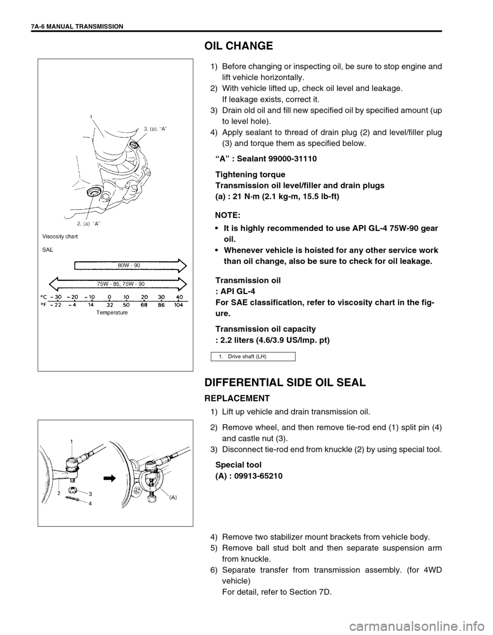
1) Before changing or inspecting oil, be sure to stop engine and
lift vehicle horizontally.
2) With vehicle lifted up, check oil level and leakage.
If leakage exists, correct it.
3) Drain old oil and fill new specified oil by specified amount (up
to level hole).
4) Apply sealant to thread of drain plug (2) and level/filler plug
(3) and torque them as specified below.
“A” : Sealant 99000-31110
Tightening torque
Transmission oil level/filler and drain plugs
(a) : 21 N·m (2.1 kg-m, 15.5 lb-ft)
Transmission oil
: API GL-4
For SAE classification, refer to viscosity chart in the fig-
ure.
Transmission oil capacity
: 2.2 liters (4.6/3.9 US/lmp. pt)
DIFFERENTIAL SIDE OIL SEAL
REPLACEMENT
1) Lift up vehicle and drain transmission oil.
2) Remove wheel, and then remove tie-rod end (1) split pin (4)
and castle nut (3).
3) Disconnect tie-rod end from knuckle (2) by using special tool.
Special tool
(A) : 09913-65210
4) Remove two stabilizer mount brackets from vehicle body.
5) Remove ball stud bolt and then separate suspension arm
from knuckle.
6) Separate transfer from transmission assembly. (for 4WD
vehicle)
For detail, refer to Section 7D. NOTE:
It is highly recommended to use API GL-4 75W-90 gear
oil.
Whenever vehicle is hoisted for any other service work
than oil change, also be sure to check for oil leakage.
1. Drive shaft (LH)
Page 40 of 447
7A-40 MANUAL TRANSMISSION
REQUIRED SERVICE MATERIAL
SPECIAL TOOL
MaterialRecommended SUZUKI product
(Part Number)Use
Lithium grease SUZUKI SUPER GREASE A
(99000-25010) Oil seal lips
O-rings
Select lever boss
Select lever shaft bush
Gear shift control cable end
Sealant SUZUKI BOND NO.1215
(99000-31110) Oil drain plug and filler/level plug
Locating spring bolts
Mating surface of transmission case
Mating surface of side cover
Gear shift interlock bolt
5th to reverse interlock guide bolt
Thread lock cement THREAD LOCK 1322
(99000-32110) Reverse gear shift lever bolts
Oil gutter bolt
Shift fork plug
Reverse shaft bolt
Final gear bolts
09900-06107 09900-20606 09900-20701 09913-60910
Snap ring pliers
(Opening type)Dial gauge Magnetic stand Bearing puller
09913-75510 09913-80112 09913-84510 09922-85811
Bearing installer Bearing installer Bearing installer Spring pin remover
4.5 mm
Page 181 of 447
AUTOMATIC TRANSMISSION (4 A/T) 7B-139
REQUIRED SERVICE MATERIAL
NOTE:
This kit includes the following items.
1. Storage case, 2. Operator’s manual, 3. SUZUKI scan tool (Tech-1A), 4. DLC cable,
5. Test lead / probe, 6. Power source cable, 7. DLC cable adaptor, 8. Self-test adaptor
MaterialRecommended SUZUKI product
(Part Number)Use
Automatic transmission fluid
An equivalent of DEXRON
®-III or
DEXRONR
®-IIEAutomatic transmission
Parts lubrication when installing
Sealant SUZUKI BOND No. 1215
(99000-31110)Case housing star-shaped recess
bolts
(3 pcs only)
Lithium grease SUZUKI SUPER GREASE C
(99000-25030)Retaining parts in place when
assembling
Oil seal lips
D-rings
O-rings
SUZUKI SUPER GREASE A
(99000-25010)Cable ends
Converter center cup
Thread lock cement THREAD LOCK 1322
(99000-32110)Final gear bolts
Torque converter housing bolts
Page 201 of 447

TRANSFER 7D-3
ON-VEHICLE SERVICE
OIL CHANGE
1) Before changing or inspecting oil, be sure to stop engine and
lift vehicle horizontally.
2) With vehicle lifted up, check oil level and leakage. If leakage
exists, correct or repair it.
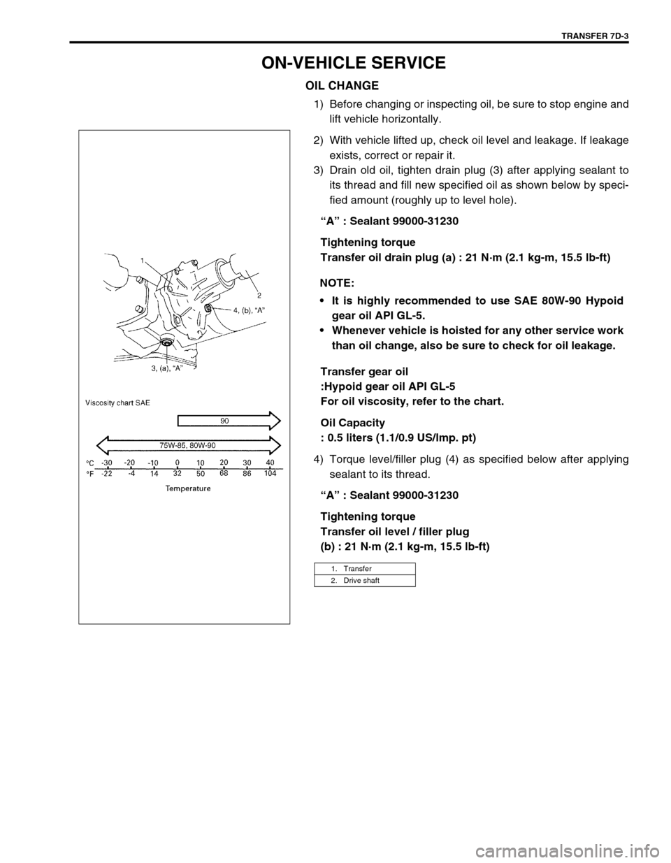
3) Drain old oil, tighten drain plug (3) after applying sealant to
its thread and fill new specified oil as shown below by speci-
fied amount (roughly up to level hole).
“A” : Sealant 99000-31230
Tightening torque
Transfer oil drain plug (a) : 21 N·m (2.1 kg-m, 15.5 lb-ft)
Transfer gear oil
:Hypoid gear oil API GL-5
For oil viscosity, refer to the chart.
Oil Capacity
: 0.5 liters (1.1/0.9 US/lmp. pt)
4) Torque level/filler plug (4) as specified below after applying
sealant to its thread.
“A” : Sealant 99000-31230
Tightening torque
Transfer oil level / filler plug
(b) : 21 N·m (2.1 kg-m, 15.5 lb-ft) NOTE:
It is highly recommended to use SAE 80W-90 Hypoid
gear oil API GL-5.
Whenever vehicle is hoisted for any other service work
than oil change, also be sure to check for oil leakage.
1. Transfer
2. Drive shaft
Page 220 of 447
7D-22 TRANSFER
TIGHTENING TORQUE SPECIFICATION
REQUIRED SERVICE MATERIAL
SPECIAL TOOL
Fastening partTightening torque
Nm kg-m lb-ft
Transfer oil level/filler and drain plugs 21 2.1 15.5
Transfer bevel gear nut 150 15.0 108.5
Transfer case bolts 23 2.3 17.0
Transfer output retainer bolts 50 5.0 36.5
Transfer mounting bolts 50 5.0 36.5
Transfer rear mounting bracket bolts 55 5.5 40.0
Transfer rear mounting bracket nuts 50 5.5 36.5
Transfer mounting bolt 55 5.5 40.0
Transfer rear mounting bracket No.2 bolts 55 5.5 40.0
Transfer stiffener bolts 50 5.0 36.5
Exhaust pipe bolts 50 5.0 36.5
MaterialRecommended SUZUKI products
(Part Number)Use
Lithium grease SUZUKI SUPER GREASE A
(99000-25010)Oil seal lips
Sealant SUZUKI BOND NO. 1216B
(99000-31230)Oil drain plug
Oil level plug
Mating surface of transfer case
09913-65135 09925-58210 09941-54911 09924-84510-005
Bearing puller Oil seal installer Bearing outer race
removerBearing installer attach-
ment
Page 226 of 447

7F-4 REAR DIFFERENTIAL
ON-VEHICLE SERVICE
OIL CHANGE
1) Before oil change or inspection, be sure to stop engine and
set vehicle horizontally.
2) Check oil level and existence of leakage. If leakage is found,
correct its cause.
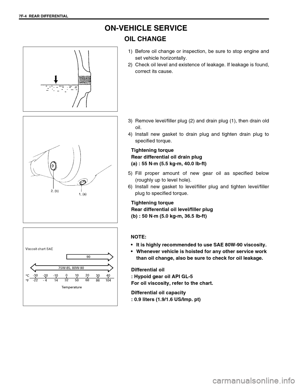
3) Remove level/filler plug (2) and drain plug (1), then drain old
oil.
4) Install new gasket to drain plug and tighten drain plug to
specified torque.
Tightening torque
Rear differential oil drain plug
(a) : 55 N·m (5.5 kg-m, 40.0 lb-ft)
5) Fill proper amount of new gear oil as specified below
(roughly up to level hole).
6) Install new gasket to level/filler plug and tighten level/filler
plug to specified torque.
Tightening torque
Rear differential oil level/filler plug
(b) : 50 N·m (5.0 kg-m, 36.5 lb-ft)
Differential oil
: Hypoid gear oil API GL-5
For oil viscosity, refer to the chart.
Differential oil capacity
: 0.9 liters (1.9/1.6 US/Imp. pt)
NOTE:
It is highly recommended to use SAE 80W-90 viscosity.
Whenever vehicle is hoisted for any other service work
than oil change, also be sure to check for oil leakage.
Page 243 of 447
REAR DIFFERENTIAL 7F-21
REQUIRED SERVICE MATERIAL
SPECIAL TOOL
MaterialRecommended SUZUKI product
(Part Number)Use
Thread lock cement THREAD LOCK CEMENT 1322
(99000-32110)Bevel gear bolts
Lithium grease SUZUKI SUPER GREASE A
(99000-25010)Oil seal lips
Sealant SUZUKI BOND NO. 1215
(99000-31110)Thread part of differential carrier bolt
Mating surface of differential housing
Mating surface of rear axle housing
Mating surface of viscous coupling case
09951-16060 09951-76010 09927-28010 09925-88210
Lower arm bush remover Bearing installer Bevel pinion holder Bearing puller attachment
09913-60910 09913-80112 09900-20701 09900-20606
Bearing puller Bearing installer Magnetic stand Dial gauge
09922-76140 09922-76150 09922-76330 09922-76430
Bevel pinion shaft Bevel pinion nut Rear collar Front collar
Page 442 of 447

10B-68 AIR BAG SYSTEM
8) Route deployment harness out the vehicle.
9) Verify that the inside of the vehicle and the area surrounding
the vehicle are clear of all people and loose or flammable
objects.
10) Stretch the deployment harness to its full length 10 m (33 ft)
(1).
Special tool
(A) : 09932-75030
11) Place a power source near the shorted end (3) of the deploy-
ment harness. Recommended application: 12 Volts mini-
mum, 2 amps minimum. A vehicle battery is suggested.
12) Completely cover windshield area and front door window
openings with a drop cloth, blanket to similar item (2). This
reduces the possibility of injury due to possible fragmenta-
tion of the vehicle’s glass or interior.
13) Notify all people in the immediate area that you intend to
deploy the air bag (inflator) module or activate the seat belt
pretensioner.
.
NOTE:
When the air bag deploys and the pretensioner acti-
vates, the rapid gas expansion will create a substantial
report. Wear suitable ear protection. Notify all people
in the immediate area that you intend to deploy the air
bag (inflator) module or to activate the seat belt preten-
sioner and suitable ear protection should be worn.
After the air bag (inflator) module has been deployed,
the surface of the air bag may contain a powdery resi-
due. This powder consists primarily of cornstarch
(used to lubricate the bag as it inflates) and by-prod-
ucts of the chemical reaction.
WARNING:
After deployment/activation, the metal surfaces of the
air bag (inflator) module and the seat belt pretensioner
will be very hot. Do not touch the metal areas of them
for about 30 minutes after deployment/activation.
Do not apply water, oil, etc. to deployed air bag (infla-
tor) module and activated seat belt pretensioner. Fail-
ure to follow procedures may result in fire or personal
injury.
1
3 2
1
32
Driver side for left hand steering vehicle
Driver side for right hand steering vehicle