2000 SUZUKI SWIFT length
[x] Cancel search: lengthPage 35 of 447

MANUAL TRANSMISSION 7A-35
11) Check locating spring for deterioration and replace with new
one as necessary.
Locating spring free length
For Low speed (3) and 5th & reverse (6)
Standard : 26.1 mm (1.028 in.)
Service Limit : 25.0 mm (0.984 in.)
For High speed (5)
Standard : 40.1 mm (1.579 in.)
Service Limit : 39.0 mm (1.535 in.)
12) Install steel ball (4) and locating spring for respective gear
shift shaft and tighten bolt (1) to which sealant have been
applied to its thread part.
Sealant 99000-31110
Tightening torque
Locating spring bolts (d) : 13 N·m (1.3 kg-m, 9.5 Ib-ft)
FIFTH GEARS
1) To seat countershaft left bearing cup (1) to bearing cone, tap
cup by using special tool and plastic hammer.
Special tool
(A) : 09913-84510
2) Put a shim (2) on bearing cup (3) provisionally, place straight
edge (1) over it and compress it by hand through straight
edge, and then measure “a” (Clearance between case sur-
face (4) and straight edge) by using feeler gauge (5).
Clearance between case surface and straight edge
“a” : 0.13 – 0.17 mm (0.0051 – 0.0067 in.)
(Shim protrusion)
3) By repeating above step, select a suitable shim which
adjusts clearance “a” to specification and put it on bearing
cup.
2. Washer
NOTE:
Insert 0.15 mm (0.0059 in.) feeler to know whether or not
a shim fulfills specification quickly.
Page 150 of 447

7B-108 AUTOMATIC TRANSMISSION (4 A/T)
Valve spring dimensions (Reference)
Lower Valve Body
1) Remove oil strainers (1).
2) Remove solenoid valves, if still attached.
3) Remove keys (2) and pull out all sleeve, plug, spring and
valves.
Valve spring dimensions (Reference)Spring Free length
“a” (mm)Outside diameter
“b” (mm)
Primary regula-
tor valve spring79.2 18.0
Lock-up control
valve spring31.1 8.5
Lock-up signal
valve spring36.1 8.5
3. Fail valve No.1 sleeve
4. Fail valve No.1
5. Cooler by-pass valve
6. Cooler by-pass valve spring
7. Manual valve
8. Secondary regulator valve
9. Secondary regulator valve spring
10. Secondary regulator valve plug
Spring Free length
“a” (mm)Outside diame-
ter “b” (mm)
Secondary regula-
tor valve spring38.7 8.8
Cooler by-pass
valve spring22.8 8.0
Page 153 of 447

AUTOMATIC TRANSMISSION (4 A/T) 7B-111
3) Assemble lower valve body with gaskets and plate over
upper valve body.
First tighten bolts A then the other bolts.
Tightening torque
Valve body bolts (a) : 5.5 N·m (0.55 kg-m, 4.0 lb-ft)
4) Install manual valve to valve body assembly.NOTE:
Be careful not to fall steel balls off.
There are four kinds of bolts fixing upper and lower
valve body. Refer to the table below for the bolt specifi-
cations.
Bolt Length “a”Pieces
A 20 mm (0.79 in.) 2
B 23 mm (0.91 in.) 2
C 29.5 mm (1.16 in.) 3
D 42 mm (1.65 in.) 5
1. Bolt A 3. Bolt C
2. Bolt B 4. Bolt D
Page 174 of 447

7B-132 AUTOMATIC TRANSMISSION (4 A/T)
56) Install valve body assembly (1) to transmission case.
First match the pin of the manual valve to the slot of the
manual shift shaft.
To fix valve body assembly (1) to transmission case, first
tighten bolt B (3), then tighten other bolts.
Tightening torque
Valve body to transmission case bolts
: 10 N·m (1.0 kg-m, 7.5 lb-ft)
57) Connect couplers of wire-to-solenoid to solenoid valves.Bolt Length “a”Pieces
A 30 mm (1.20 in.) 7
B 31 mm (1.22 in.) 2
C 25 mm (0.98 in.) 2
2. Bolt A
4. Bolt C
5. Manual valve pin
6. Slot of manual shift shaft
Solenoid Valve Wire Color
A (No.1) White
B (No.2) Black
C (No.3) Red
D (No.4) Yellow
E (No.5) Brown
TCC (Lock-up) Orange
1. Solenoid valve No.1
2. Solenoid valve No.2
3. Solenoid valve No.3
4. Solenoid valve No.4
5. Solenoid valve No.5
6. Lock-up solenoid
Page 300 of 447

8G-22 IMMOBILIZER CONTROL SYSTEM
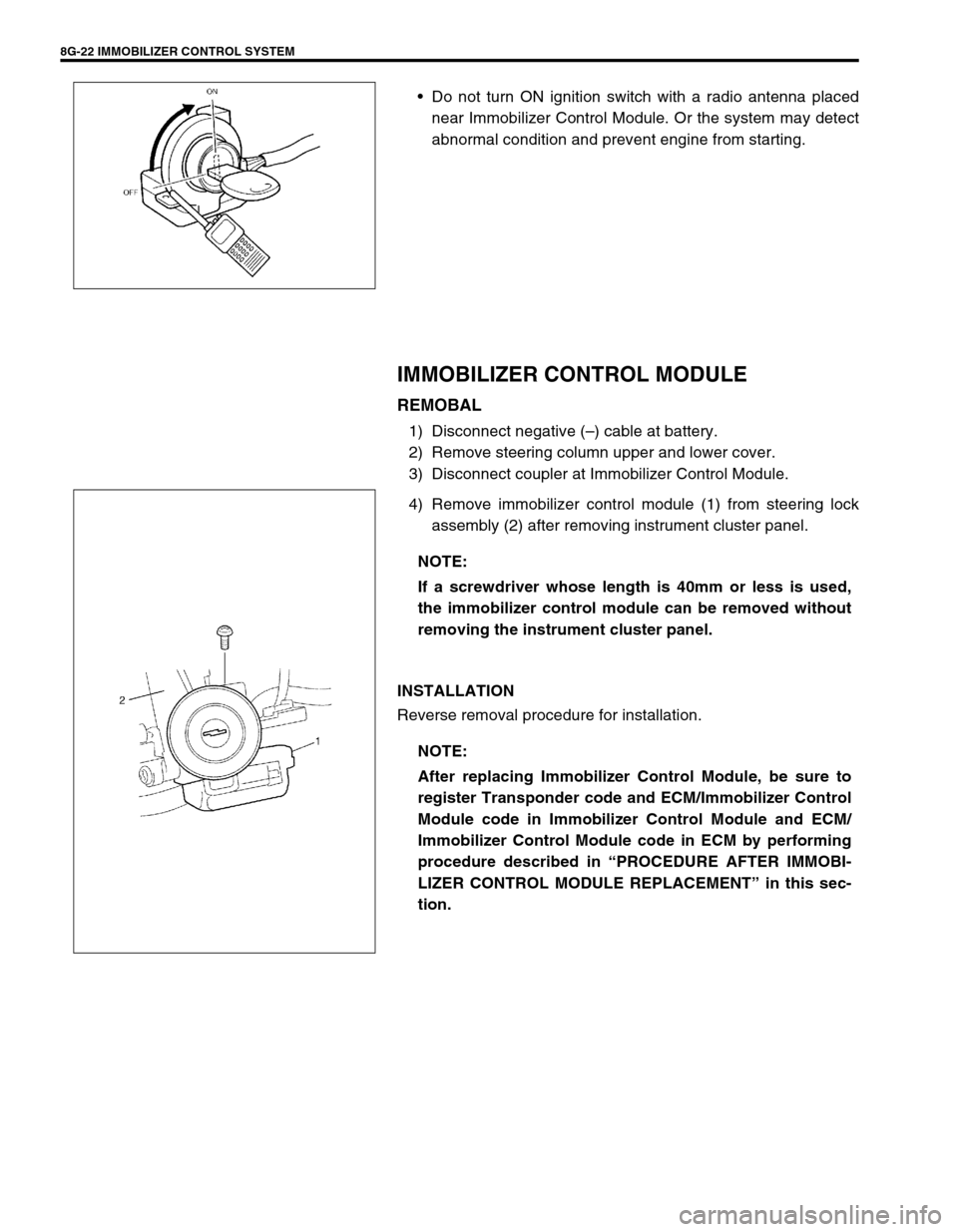
Do not turn ON ignition switch with a radio antenna placed
near Immobilizer Control Module. Or the system may detect
abnormal condition and prevent engine from starting.
IMMOBILIZER CONTROL MODULE
REMOBAL
1) Disconnect negative (–) cable at battery.
2) Remove steering column upper and lower cover.
3) Disconnect coupler at Immobilizer Control Module.
4) Remove immobilizer control module (1) from steering lock
assembly (2) after removing instrument cluster panel.
INSTALLATION
Reverse removal procedure for installation.
NOTE:
If a screwdriver whose length is 40mm or less is used,
the immobilizer control module can be removed without
removing the instrument cluster panel.
NOTE:
After replacing Immobilizer Control Module, be sure to
register Transponder code and ECM/Immobilizer Control
Module code in Immobilizer Control Module and ECM/
Immobilizer Control Module code in ECM by performing
procedure described in “PROCEDURE AFTER IMMOBI-
LIZER CONTROL MODULE REPLACEMENT” in this sec-
tion.
Page 427 of 447

AIR BAG SYSTEM 10B-53
REPAIRS AND INSPECTIONS REQUIRED AFTER AN ACCIDENT
ACCIDENT WITH DEPLOYMENT/ACTIVA-
TION - COMPONENT REPLACEMENT
The following components must be replaced.
Driver and passenger air bag (inflator) modules
Driver and passenger seat belt pretensioners
SDM
–Replace with new one as an assembly.
ACCIDENT WITH OR WITHOUT DEPLOY-
MENT/ACTIVATION - COMPONENT INSPEC-
TIONS
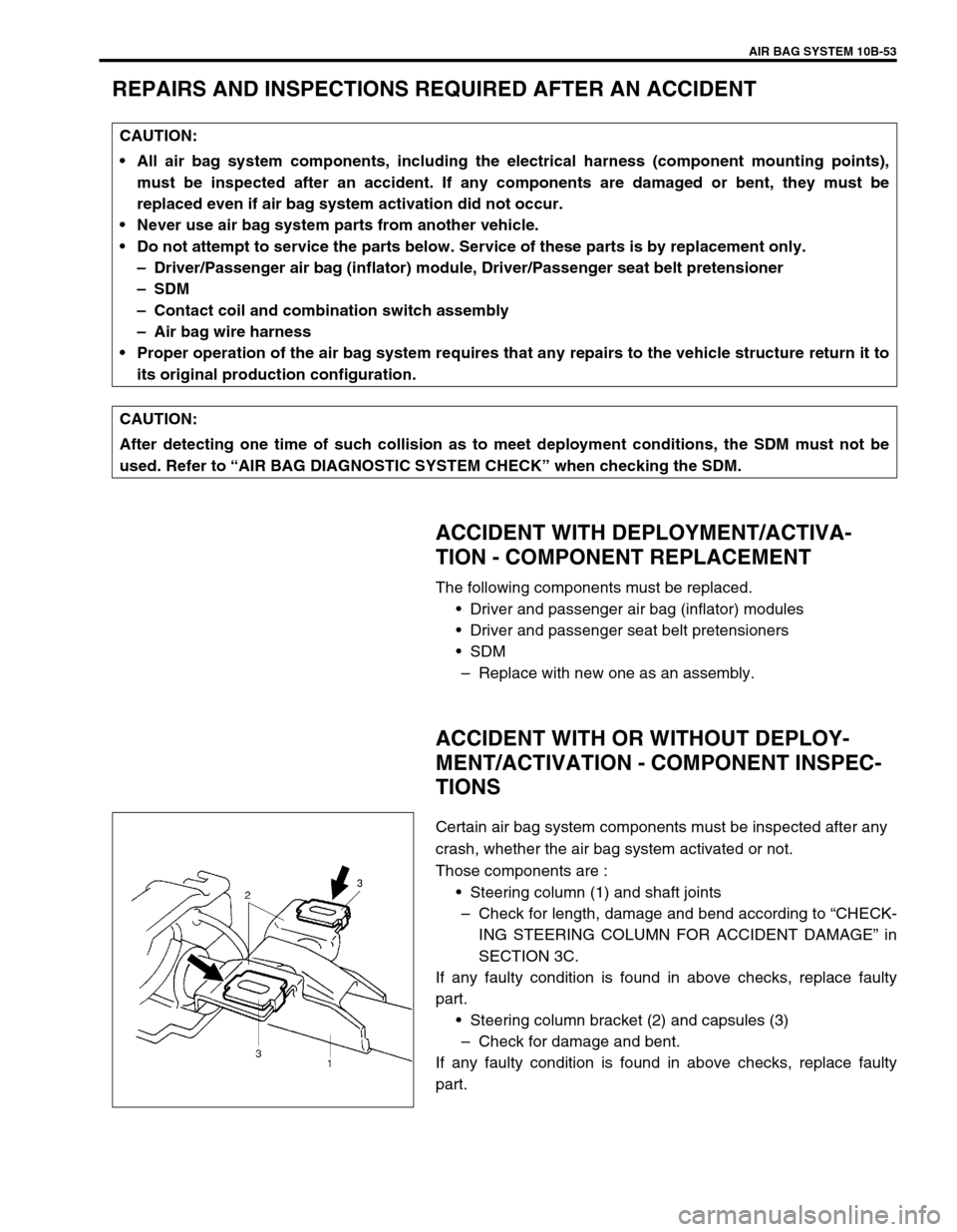
Certain air bag system components must be inspected after any
crash, whether the air bag system activated or not.
Those components are :
Steering column (1) and shaft joints
–Check for length, damage and bend according to “CHECK-
ING STEERING COLUMN FOR ACCIDENT DAMAGE” in
SECTION 3C.
If any faulty condition is found in above checks, replace faulty
part.
Steering column bracket (2) and capsules (3)
–Check for damage and bent.
If any faulty condition is found in above checks, replace faulty
part. CAUTION:
All air bag system components, including the electrical harness (component mounting points),
must be inspected after an accident. If any components are damaged or bent, they must be
replaced even if air bag system activation did not occur.
Never use air bag system parts from another vehicle.
Do not attempt to service the parts below. Service of these parts is by replacement only.
–Driver/Passenger air bag (inflator) module, Driver/Passenger seat belt pretensioner
–SDM
–Contact coil and combination switch assembly
–Air bag wire harness
Proper operation of the air bag system requires that any repairs to the vehicle structure return it to
its original production configuration.
CAUTION:
After detecting one time of such collision as to meet deployment conditions, the SDM must not be
used. Refer to “AIR BAG DIAGNOSTIC SYSTEM CHECK” when checking the SDM.
Page 438 of 447

10B-64 AIR BAG SYSTEM
6) Stretch the deployment harness from the driver or passen-
ger air bag (inflator) module to its full length 10 m (33 ft) (1).
Special tool
(A) : 09932-75030
7) Place a power source (3) near the shorted end of the deploy-
ment harness. Recommended application: 12 Volts mini-
mum, 2 amps minimum. A vehicle battery is suggested.
8) Verify that the area around the air bag (inflator) module or
seat belt pretensioner is clear of all people and loose or flam-
mable objects.
9) Verify setting condition of air bag (inflator) module or preten-
sioner as follows.
[In case of driver air bag (inflater) module]
Verify that the driver air bag (inflator) module is resting with
its vinyl trim cover facing up.
[In case of passenger air bag (inflator) module]
Verify that the passenger air bag (inflator) module is firmly
and properly secured in passenger air bag (inflator) module
deployment fixture (special tool).
[In case of seat belt pretensioner]
Verify that the seat belt pretensioner, is placed as shown in
the figure on the ground in the space just cleared.
10) Connect (2) the air bag (inflator) module or seat belt preten-
sioner to the deployment harness connector and lock con-
nector with lock lever.
11) Notify all people in the immediate area that you intend to
deploy/activate the air bag (inflator) module or seat belt pre-
tensioner.
NOTE:
When the air bag deploys and the pretensioner acti-
vates, the rapid gas expansion will create a substantial
report. Wear suitable ear protection. Notify all people
in the immediate area that you intend to deploy the air
bag (inflator) module or activate the seat belt preten-
sioner and suitable ear protection should be worn.
When the driver air bag deploys and the pretensioner
activates, driver air bag (inflator) module and preten-
sioner (retractor assembly) may jump about 30 cm (1
ft) vertically. This is a normal reaction of them to the
force of the rapid gas expansion inside the air bag and
pretensioner.
After the air bag (inflator) module has been deployed,
the surface of the air bag may contain a powdery resi-
due. This powder consists primarily of cornstarch
(used to lubricate the bag as it inflates) and by-prod-
ucts of the chemical reaction.
Page 442 of 447

10B-68 AIR BAG SYSTEM
8) Route deployment harness out the vehicle.
9) Verify that the inside of the vehicle and the area surrounding
the vehicle are clear of all people and loose or flammable
objects.
10) Stretch the deployment harness to its full length 10 m (33 ft)
(1).
Special tool
(A) : 09932-75030
11) Place a power source near the shorted end (3) of the deploy-
ment harness. Recommended application: 12 Volts mini-
mum, 2 amps minimum. A vehicle battery is suggested.
12) Completely cover windshield area and front door window
openings with a drop cloth, blanket to similar item (2). This
reduces the possibility of injury due to possible fragmenta-
tion of the vehicle’s glass or interior.
13) Notify all people in the immediate area that you intend to
deploy the air bag (inflator) module or activate the seat belt
pretensioner.
.
NOTE:
When the air bag deploys and the pretensioner acti-
vates, the rapid gas expansion will create a substantial
report. Wear suitable ear protection. Notify all people
in the immediate area that you intend to deploy the air
bag (inflator) module or to activate the seat belt preten-
sioner and suitable ear protection should be worn.
After the air bag (inflator) module has been deployed,
the surface of the air bag may contain a powdery resi-
due. This powder consists primarily of cornstarch
(used to lubricate the bag as it inflates) and by-prod-
ucts of the chemical reaction.
WARNING:
After deployment/activation, the metal surfaces of the
air bag (inflator) module and the seat belt pretensioner
will be very hot. Do not touch the metal areas of them
for about 30 minutes after deployment/activation.
Do not apply water, oil, etc. to deployed air bag (infla-
tor) module and activated seat belt pretensioner. Fail-
ure to follow procedures may result in fire or personal
injury.
1
3 2
1
32
Driver side for left hand steering vehicle
Driver side for right hand steering vehicle