Page 7 of 447

MANUAL TRANSMISSION 7A-7
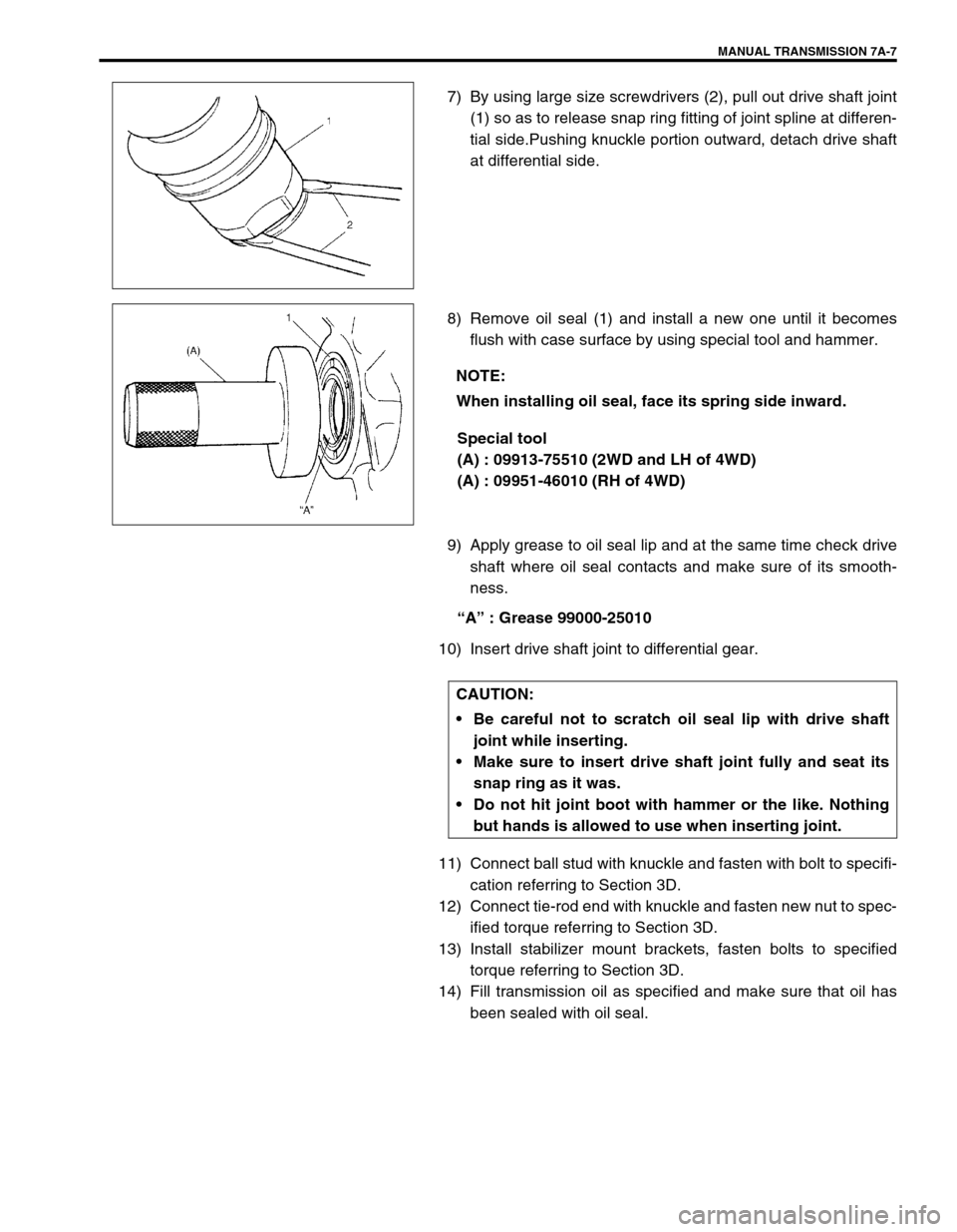
7) By using large size screwdrivers (2), pull out drive shaft joint
(1) so as to release snap ring fitting of joint spline at differen-
tial side.Pushing knuckle portion outward, detach drive shaft
at differential side.
8) Remove oil seal (1) and install a new one until it becomes
flush with case surface by using special tool and hammer.
Special tool
(A) : 09913-75510 (2WD and LH of 4WD)
(A) : 09951-46010 (RH of 4WD)
9) Apply grease to oil seal lip and at the same time check drive
shaft where oil seal contacts and make sure of its smooth-
ness.
“A” : Grease 99000-25010
10) Insert drive shaft joint to differential gear.
11) Connect ball stud with knuckle and fasten with bolt to specifi-
cation referring to Section 3D.
12) Connect tie-rod end with knuckle and fasten new nut to spec-
ified torque referring to Section 3D.
13) Install stabilizer mount brackets, fasten bolts to specified
torque referring to Section 3D.
14) Fill transmission oil as specified and make sure that oil has
been sealed with oil seal.
NOTE:
When installing oil seal, face its spring side inward.
CAUTION:
Be careful not to scratch oil seal lip with drive shaft
joint while inserting.
Make sure to insert drive shaft joint fully and seat its
snap ring as it was.
Do not hit joint boot with hammer or the like. Nothing
but hands is allowed to use when inserting joint.
Page 8 of 447
7A-8 MANUAL TRANSMISSION
GEAR SHIFT CONTROL LEVER AND CABLE
1. Gear shift control lever knob 5. Gear select control cable 9. Cable bracket bolt
2. Lever boot holder 6. Gear shift control cable guide nut 10. Cable grommet
3. Gear shift lever boot 7. Gear shift control lever assembly 11. E-ring
4. Gear shift control cable
: Apply SUZUKI SUPER GREASE A 99000-25010 to con-
necting portion of gear shift control cable8. Cable mounting bolt Tightening torque
Page 187 of 447
CLUTCH 7C-5
INSPECTION
Inspect clutch cable and replace it for any of the following condi-
tions.
Excessive cable friction
Frayed cable
Bent or kinked cable
Broken boots
Worn end
INSTALLATION
1) Apply grease to cable end hook and also joint pin before
installing cable.
“A” : Grease 99000-25010
2) Hook cable end with pedal by using screwdriver or long nose
pliers from cabin inside, then join inner cable wire joint pin in
release lever.
3) Install clutch cable (2) to bracket (3) by turning cable cap (1)
about 90° as shown.
4) Screw in joint nut and adjust free travel of pedal to specifica-
tion by turning nut.
5) Check clutch for proper function with engine running.
NOTE:
Take care that cable grommet (4) has specific installing
direction as shown in the figure.