Page 115 of 447
AUTOMATIC TRANSMISSION (4 A/T) 7B-73
REMOVAL
1) Disconnect negative cable at battery and disable air bag sys-
tem, referring to “DISABLING AIR BAG SYSTEMS” in Sec-
tion 10B (if equipped).
2) Remove steering column hole cover and steering column
cover.
3) Remove steering column mounting bolts and nuts.
4) Remove interlock cable screw (1) located at ignition switch
and disconnect interlock cable (2) from key cylinder arm (3)
with ignition switch turned to “ACC” position.
5) Remove center console.
6) Remove cable end (1) from key interlock cam (2) and its
bracket (3).
7) Remove interlock cable (4).
INSTALLATION
1) Install interlock cable (1) to pedal brackets (2) by clamp as
shown in figure.
2) With ignition key at “ACC” position, connect cable end (1) to
key cylinder arm (2) and tighten cable screw (3) securely.
Page 116 of 447
7B-74 AUTOMATIC TRANSMISSION (4 A/T)
3) If selector lever is in “P” range, shift selector lever to other
than “P” range with releasing shift lock referring to “SHIFT
LOCK SOLENOID MANUAL RELEASE” in this section.
4) Install cable end (1) and cable casing cap (2) to key interlock
cam (3) and its bracket (4), then install cable (5) to selector
pad (6).
5) With selector lever set at “P” position, turn ignition key to
“ACC” position and then check for following conditions.
With knob button released, ignition key can be turned from
“ACC” position to “LOCK” position.
With knob button pressed, ignition key cannot be turned from
“ACC” position to “LOCK” position.
6) Install steering column referring to Section 3C.
7) Install steering column hole cover.
8) Install center console.
9) Connect negative cable at battery and enable air bag sys-
tem, referring to “ENABLING AIR BAG SYSTEM” in Section
10B (if equipped).
Page 276 of 447

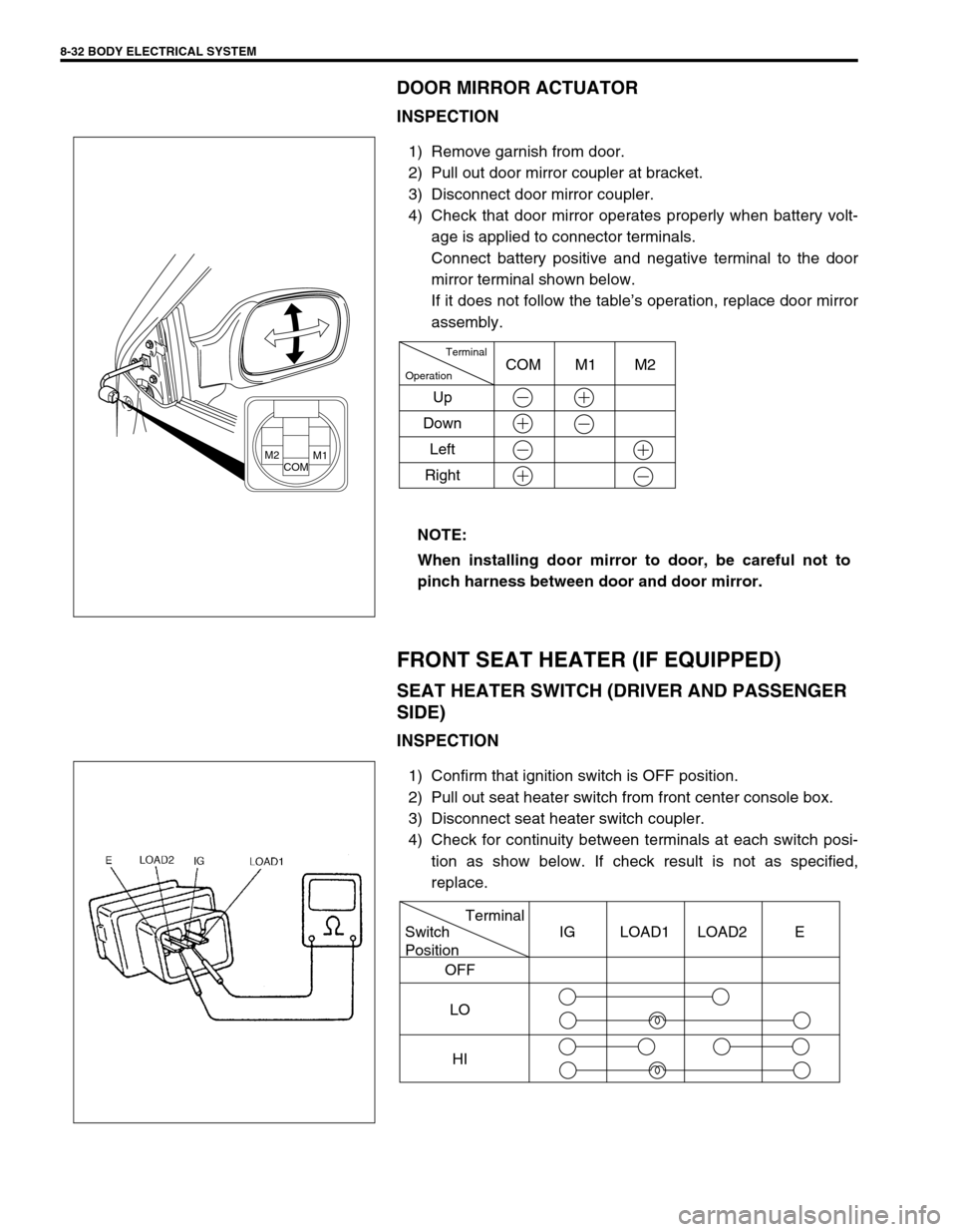
8-32 BODY ELECTRICAL SYSTEM
DOOR MIRROR ACTUATOR
INSPECTION
1) Remove garnish from door.
2) Pull out door mirror coupler at bracket.
3) Disconnect door mirror coupler.
4) Check that door mirror operates properly when battery volt-
age is applied to connector terminals.
Connect battery positive and negative terminal to the door
mirror terminal shown below.
If it does not follow the table’s operation, replace door mirror
assembly.
FRONT SEAT HEATER (IF EQUIPPED)
SEAT HEATER SWITCH (DRIVER AND PASSENGER
SIDE)
INSPECTION
1) Confirm that ignition switch is OFF position.
2) Pull out seat heater switch from front center console box.
3) Disconnect seat heater switch coupler.
4) Check for continuity between terminals at each switch posi-
tion as show below. If check result is not as specified,
replace. NOTE:
When installing door mirror to door, be careful not to
pinch harness between door and door mirror.
M2COMM1
Terminal
Operation
UpCOM M1 M2
Down
Left
Right
Terminal
Switch
Position
OFF
LO
HIIG LOAD1 LOAD2 E
Page 351 of 447
BODY SERVICE 9-47
IGNITION SWITCH LOCK CYLINDER
REMOVAL AND INSTALLATION
Refer to “STEERING LOCK ASSEMBLY (IGNITION SWITCH)” in
Section 3C.
ELECTRICAL DIAGNOSIS
For ignition switch electrical troubleshooting, refer to “IGNITION
SWITCH” in Section 8.
EXTERIOR AND INTERIOR TRIM
FLOOR CARPET
REMOVAL
1) Remove front seats and rear seat cushion.
2) Remove seat belt lower anchor bolt.
3) Remove dash side trims, front side sill scuffs, center pillar inner lower trims, quarter inner trims and rear side
sill scuffs.
4) Remove parking brake lever cover and console box.
5) Remove floor carpet.
INSTALLATION
Reverse removal sequence to install front floor carpet, noting the following instruction.
For tightening torque of seat belt anchor bolt, refer to “FRONT SEAT BELT” in Section 10.
1. Floor carpet
2. Dash panel silencer
3. Silencer seat
Page 430 of 447
10B-56 AIR BAG SYSTEM
SDM
REMOVAL
1) Disconnect negative cable at battery.
2) Disable air bag system. Refer to “DISABLING AIR BAG
SYSTEM” of “SERVICE PRECAUTIONS”.
3) Remove center console boxes (1) by removing screws and
clips.
4) Disconnect SDM connector (2) from SDM (3).
5) Remove SDM (3) (with SDM plate (5)) as an assembly from
vehicle. WARNING:
During service procedures, be very careful when han-
dling a Sensing and Diagnostic Module (SDM).
Be sure to read “SERVICE PRECAUTIONS” before start-
ing to work and observe every precaution during work.
Neglecting them may result in personal injury or inactiva-
tion of the air bag system when necessary.
CAUTION:
Do not separate SDM (3) and SDM plate (5).
3
5
2 FORWARD