2000 SUZUKI SWIFT battery location
[x] Cancel search: battery locationPage 1 of 447

MANUAL TRANSMISSION 7A-1
6F1
6F2
6G
6H
6K
7A1
7B1
7C1
7A
7E
7F
8A
8B
8C
8D
8E
9
10
10A
10B
SECTION 7A
MANUAL TRANSMISSION
CONTENTS
GENERAL DESCRIPTION .............................. 7A-2
CONSTRUCTION AND SERVICING ........... 7A-2
TRANSMISSION FOR 2WD MODEL....... 7A-3
TRANSMISSION FOR 4WD MODEL....... 7A-4
DIAGNOSIS ..................................................... 7A-5
ON-VEHICLE SERVICE .................................. 7A-5
OIL CHANGE ............................................... 7A-6
DIFFERENTIAL SIDE OIL SEAL ................. 7A-6
GEAR SHIFT CONTROL LEVER AND
CABLE ......................................................... 7A-8
VEHICLE SPEED SENSOR (VSS) ............ 7A-10
UNIT REPAIR OVERHAUL ........................... 7A-11
TRANSMISSION UNIT............................... 7A-11
TRASMISSION CASE ................................ 7A-12
INPUT & COUNTER SHAFT...................... 7A-13
GEAR SHIFTER & DIFFERENTIAL ........... 7A-14
TRANSMISSION UNIT............................... 7A-16
UNIT DISASSEMBLY ................................ 7A-17
FIFTH GEARS........................................ 7A-17GEAR SHIFTER, INPUT SHAFT AND
COUNTER SHAFT................................. 7A-19
RIGHT CASE ......................................... 7A-20
SUB ASSEMBLY SERVICE ...................... 7A-21
RIGHT CASE ......................................... 7A-21
LEFT CASE............................................ 7A-21
INPUT SHAFT ASSEMBLY ................... 7A-22
COUNTER SHAFT ASSEMBLY ............ 7A-25
GEAR SHIFTER..................................... 7A-29
DIFFERENTIAL ASSEMBLY ................. 7A-30
UNIT ASSEMBLY ...................................... 7A-33
DIFFERENTIAL TO LEFT CASE ........... 7A-33
FIFTH GEARS ....................................... 7A-35
GEAR SHIFT AND SELECT SHAFT
ASSEMBLY ............................................ 7A-38
TIGHTENING TORQUE SPECIFICATION.... 7A-39
REQUIRED SERVICE MATERIAL................ 7A-40
SPECIAL TOOL ............................................ 7A-40
WARNING:
For vehicles equipped with Supplemental Restraint (Air Bag) System :
• Service on and around the air bag system components or wiring must be performed only by an
authorized SUZUKI dealer. Refer to “Air Bag System Components and Wiring Location View” under
“General Description” in air bag system section in order to confirm whether you are performing ser-
vice on or near the air bag system components or wiring. Please observe all WARNINGS and “Ser-
vice Precautions” under “On-Vehicle Service” in air bag system section before performing service
on or around the air bag system components or wiring. Failure to follow WARNINGS could result in
unintentional activation of the system or could render the system inoperative. Either of these two
conditions may result in severe injury.
Technical service work must be started at least 90 seconds after the ignition switch is turned to the
“LOCK” position and the negative cable is disconnected from the battery. Otherwise, the system
may be activated by reserve energy in the Sensing and Diagnostic Module (SDM).
Page 43 of 447

AUTOMATIC TRANSMISSION (4 A/T) 7B-1
6F1
6F2
6G
6H
6K
7A
7A1
7C1
7D
7B
7F
8A
8B
8C
8D
8E
9
10
10A
10B
SECTION 7B
AUTOMATIC TRANSMISSION (4 A/T)
CONTENTS
GENERAL DESCRIPTION ...............................7B-3
ELECTRONIC SHIFT CONTROL SYSTEM . 7B-6
TRANSMISSION CONTROL MODULE
(TCM) ........................................................ 7B-7
FAIL SAFE FUNCTION ............................. 7B-8
CHANGE MECHANISM .......................... 7B-10
AUTOMATIC GEAR SHIFT DIAGRAM ... 7B-11
DIAGNOSIS ....................................................7B-13
AUTOMATIC TRANSMISSION
DIAGNOSTIC FLOW TABLE ...................... 7B-13
TROUBLE DIAGNOSIS TABLE .................. 7B-18
STALL TEST ........................................... 7B-20
TIME LAG TEST ..................................... 7B-21
LINE PRESSURE TEST ......................... 7B-22
ENGINE BRAKE TEST ........................... 7B-23
“P” RANGE TEST.................................... 7B-23
ELECTRONIC CONTROL SYSTEM
DIAGNOSIS ................................................ 7B-24
PRECAUTIONS IN DIAGNOSING
TROUBLES ............................................. 7B-24
DTC CHECK ........................................... 7B-25
DTC CLEARANCE .................................. 7B-27
DTC TABLE............................................. 7B-28
TCM POWER AND GROUND CIRCUIT
CHECK .................................................... 7B-30
DTC P0715 (DTC NO.14) INPUT/
TURBINE SPEED SENSOR CIRCUIT
MALFUNCTION ...................................... 7B-31
DTC P0730 (DTC NO. 18) INCORRECT
GEAR RATIO .......................................... 7B-33
DTC P0753 (DTC NO.21/22) SHIFT
SOLENOID-A (NO.1) ELECTRICAL ....... 7B-35DTC P0758 (DTC NO.23/24) SHIFT
SOLENOID-B (NO.2) ELECTRICAL ....... 7B-35
DTC P0743 (DTC NO.25/26) TCC
(LOCK-UP CLUTCH) SYSTEM
ELECTRICAL .......................................... 7B-35
DTC P0741 (DTC NO.29) TCC
(LOCK-UP) SOLENOID
PERFORMANCE OR STUCK OFF ........ 7B-37
DTC P0720 (DTC NO. 31) OUTPUT
SHAFT SPEED SENSOR CIRCUIT
MALFUNCTION ...................................... 7B-38
DTC P1700 (DTC NO.32/33)
THROTTLE POSITION SIGNAL INPUT
MALFUNCTION ...................................... 7B-41
DTC P0705 (DTC NO.34)
TRANSMISSION RANGE SENSOR
(SWITCH) CIRCUIT MALFUNCTION ..... 7B-43
DTC P0725 (DTC NO.35) ENGINE
SPEED INPUT CIRCUIT
MALFUNCTION ...................................... 7B-45
DTC P0710 (DTC No.36/38)
TRANSMISSION TEMPERATURE
SENSOR CIRCUIT MALFUNCTION ...... 7B-47
DTC P0763 (DTC NO.43) SHIFT
SOLENOID-C (NO.3) ELECTRICAL ....... 7B-49
DTC P0768 (DTC NO.45) SHIFT
SOLENOID-B (NO.4) ELECTRICAL ....... 7B-49
DTC P0773 (DTC NO.48) SHIFT
SOLENOID-E (NO.5) ELECTRICAL ....... 7B-49
DTC P1709 (DTC NO.51) ENGINE
COOLANT TEMPERATURE/BAROMETRIC
PRESSURE SIGNAL CIRCUIT............... 7B-51 WARNING:
For vehicles equipped with Supplemental Restraint (Air Bag) System :
Service on and around the air bag system components or wiring must be performed only by an
authorized SUZUKI dealer. Refer to “Air Bag System Components and Wiring Location View” under
“General Description” in air bag system section in order to confirm whether you are performing ser-
vice on or near the air bag system components or wiring. Please observe all WARNINGS and “Ser-
vice Precautions” under “On-Vehicle Service” in air bag system section before performing service
on or around the air bag system components or wiring. Failure to follow WARNINGS could result in
unintentional activation of the system or could render the system inoperative. Either of these two
conditions may result in severe injury.
Technical service work must be started at least 90 seconds after the ignition switch is turned to the
“LOCK” position and the negative cable is disconnected from the battery. Otherwise, the system
may be activated by reserve energy in the Sensing and Diagnostic Module (SDM).
Page 183 of 447

CLUTCH 7C-1
6F1
6F2
6G
6H
6K
7A1
7B1
7C1
7D
7E
7C
8A
8B
8C
8D
8E
9
10
10A
10B
SECTION 7C
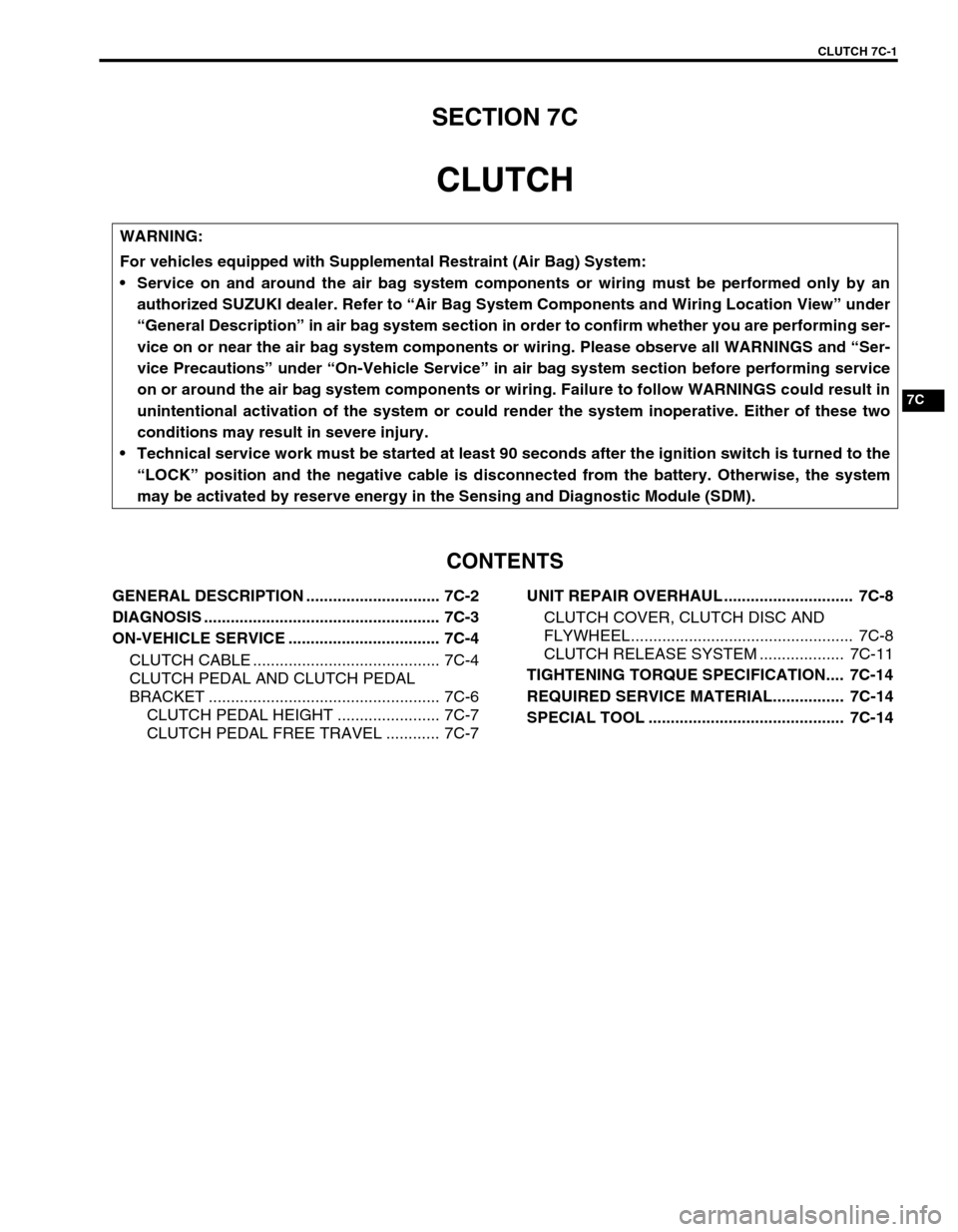
CLUTCH
CONTENTS
GENERAL DESCRIPTION .............................. 7C-2
DIAGNOSIS ..................................................... 7C-3
ON-VEHICLE SERVICE .................................. 7C-4
CLUTCH CABLE .......................................... 7C-4
CLUTCH PEDAL AND CLUTCH PEDAL
BRACKET .................................................... 7C-6
CLUTCH PEDAL HEIGHT ....................... 7C-7
CLUTCH PEDAL FREE TRAVEL ............ 7C-7UNIT REPAIR OVERHAUL ............................. 7C-8
CLUTCH COVER, CLUTCH DISC AND
FLYWHEEL.................................................. 7C-8
CLUTCH RELEASE SYSTEM ................... 7C-11
TIGHTENING TORQUE SPECIFICATION.... 7C-14
REQUIRED SERVICE MATERIAL................ 7C-14
SPECIAL TOOL ............................................ 7C-14
WARNING:
For vehicles equipped with Supplemental Restraint (Air Bag) System:
Service on and around the air bag system components or wiring must be performed only by an
authorized SUZUKI dealer. Refer to “Air Bag System Components and Wiring Location View” under
“General Description” in air bag system section in order to confirm whether you are performing ser-
vice on or near the air bag system components or wiring. Please observe all WARNINGS and “Ser-
vice Precautions” under “On-Vehicle Service” in air bag system section before performing service
on or around the air bag system components or wiring. Failure to follow WARNINGS could result in
unintentional activation of the system or could render the system inoperative. Either of these two
conditions may result in severe injury.
Technical service work must be started at least 90 seconds after the ignition switch is turned to the
“LOCK” position and the negative cable is disconnected from the battery. Otherwise, the system
may be activated by reserve energy in the Sensing and Diagnostic Module (SDM).
Page 245 of 447

BODY ELECTRICAL SYSTEM 8-1
6F1
6F2
6G
6H
6K
7A
7A1
7B1
7C1
7D
7E
7F
8A
8
8D
8E
9
10
10A
10B
SECTION 8
BODY ELECTRICAL SYSTEM
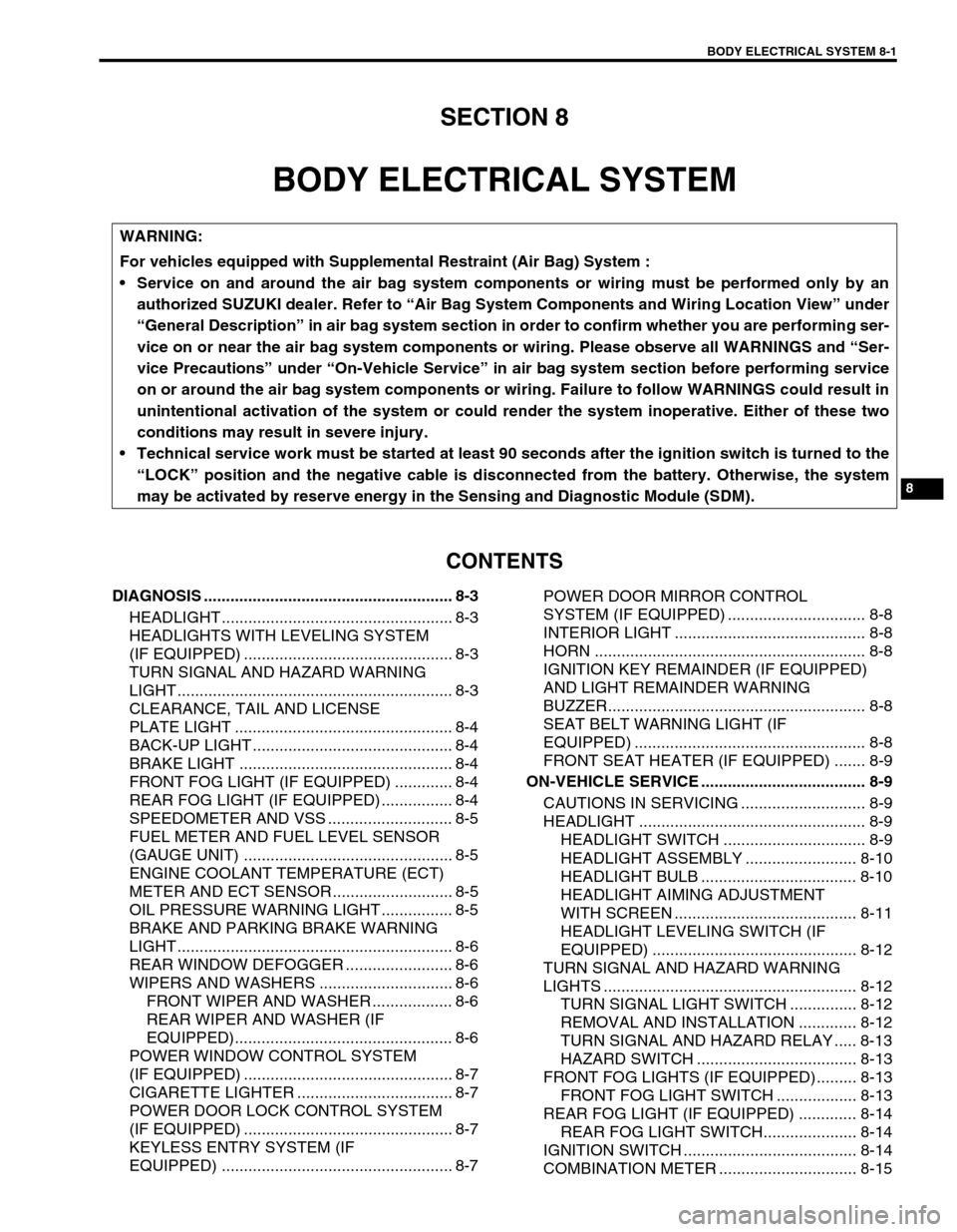
CONTENTS
DIAGNOSIS ........................................................ 8-3
HEADLIGHT .................................................... 8-3
HEADLIGHTS WITH LEVELING SYSTEM
(IF EQUIPPED) ............................................... 8-3
TURN SIGNAL AND HAZARD WARNING
LIGHT .............................................................. 8-3
CLEARANCE, TAIL AND LICENSE
PLATE LIGHT ................................................. 8-4
BACK-UP LIGHT ............................................. 8-4
BRAKE LIGHT ................................................ 8-4
FRONT FOG LIGHT (IF EQUIPPED) ............. 8-4
REAR FOG LIGHT (IF EQUIPPED) ................ 8-4
SPEEDOMETER AND VSS ............................ 8-5
FUEL METER AND FUEL LEVEL SENSOR
(GAUGE UNIT) ............................................... 8-5
ENGINE COOLANT TEMPERATURE (ECT)
METER AND ECT SENSOR ........................... 8-5
OIL PRESSURE WARNING LIGHT ................ 8-5
BRAKE AND PARKING BRAKE WARNING
LIGHT .............................................................. 8-6
REAR WINDOW DEFOGGER ........................ 8-6
WIPERS AND WASHERS .............................. 8-6
FRONT WIPER AND WASHER .................. 8-6
REAR WIPER AND WASHER (IF
EQUIPPED)................................................. 8-6
POWER WINDOW CONTROL SYSTEM
(IF EQUIPPED) ............................................... 8-7
CIGARETTE LIGHTER ................................... 8-7
POWER DOOR LOCK CONTROL SYSTEM
(IF EQUIPPED) ............................................... 8-7
KEYLESS ENTRY SYSTEM (IF
EQUIPPED) .................................................... 8-7POWER DOOR MIRROR CONTROL
SYSTEM (IF EQUIPPED) ............................... 8-8
INTERIOR LIGHT ........................................... 8-8
HORN ............................................................. 8-8
IGNITION KEY REMAINDER (IF EQUIPPED)
AND LIGHT REMAINDER WARNING
BUZZER.......................................................... 8-8
SEAT BELT WARNING LIGHT (IF
EQUIPPED) .................................................... 8-8
FRONT SEAT HEATER (IF EQUIPPED) ....... 8-9
ON-VEHICLE SERVICE ..................................... 8-9
CAUTIONS IN SERVICING ............................ 8-9
HEADLIGHT ................................................... 8-9
HEADLIGHT SWITCH ................................ 8-9
HEADLIGHT ASSEMBLY ......................... 8-10
HEADLIGHT BULB ................................... 8-10
HEADLIGHT AIMING ADJUSTMENT
WITH SCREEN ......................................... 8-11
HEADLIGHT LEVELING SWITCH (IF
EQUIPPED) .............................................. 8-12
TURN SIGNAL AND HAZARD WARNING
LIGHTS ......................................................... 8-12
TURN SIGNAL LIGHT SWITCH ............... 8-12
REMOVAL AND INSTALLATION ............. 8-12
TURN SIGNAL AND HAZARD RELAY ..... 8-13
HAZARD SWITCH .................................... 8-13
FRONT FOG LIGHTS (IF EQUIPPED)......... 8-13
FRONT FOG LIGHT SWITCH .................. 8-13
REAR FOG LIGHT (IF EQUIPPED) ............. 8-14
REAR FOG LIGHT SWITCH..................... 8-14
IGNITION SWITCH ....................................... 8-14
COMBINATION METER ............................... 8-15 WARNING:
For vehicles equipped with Supplemental Restraint (Air Bag) System :
Service on and around the air bag system components or wiring must be performed only by an
authorized SUZUKI dealer. Refer to “Air Bag System Components and Wiring Location View” under
“General Description” in air bag system section in order to confirm whether you are performing ser-
vice on or near the air bag system components or wiring. Please observe all WARNINGS and “Ser-
vice Precautions” under “On-Vehicle Service” in air bag system section before performing service
on or around the air bag system components or wiring. Failure to follow WARNINGS could result in
unintentional activation of the system or could render the system inoperative. Either of these two
conditions may result in severe injury.
Technical service work must be started at least 90 seconds after the ignition switch is turned to the
“LOCK” position and the negative cable is disconnected from the battery. Otherwise, the system
may be activated by reserve energy in the Sensing and Diagnostic Module (SDM).
Page 279 of 447

IMMOBILIZER CONTROL SYSTEM 8G-1
6F1
6F2
6G
6H
6K
7A
7A1
7B1
7C1
7D
7E
7F
8A
8B
8C
8D
8G
9
10
10A
10B
SECTION 8G
IMMOBILIZER CONTROL SYSTEM
CONTENTS
GENERAL DESCRIPTION ............................. 8G-2
WIRING CIRCUIT ....................................... 8G-3
ON-BOARD DIAGNOSTIC SYSTEM
(SELF-DIAGNOSIS FUNCTION) ................ 8G-4
DIAGNOSIS .................................................... 8G-5
PRECAUTIONS IN DIAGNOSING
TROUBLES ................................................. 8G-5
PRECAUTIONS IN IDENTIFYING
DIAGNOSTIC TROUBLE CODE............. 8G-5
DIAGNOSTIC FLOW TABLE ...................... 8G-6
DIAGNOSTIC TROUBLE CODE (DTC)
CHECK
(IMMOBILIZER CONTROL MODULE)........ 8G-7
DIAGNOSTIC TROUBLE CODE (DTC)
CHECK (ECM) ............................................ 8G-8
DIAGNOSTIC TROUBLE CODE TABLE .... 8G-9
TABLE A - IMMOBILIZER INDICATOR
LAMP CHECK (IMMOBILIZER INDICATOR
LAMP DOES NOT LIGHT AT IGNITION
SWITCH ON) ............................................ 8G-10
TABLE B - IMMOBILIZER INDICATOR
LAMP CHECK (IMMOBILIZER INDICATOR
LAMP REMAINS ON AFTER ENGINE
STARTS) ................................................... 8G-11
TABLE C - DTC IS NOT OUTPUT FROM
IMMOBILIZER CONTROL MODULE ........ 8G-12
DTC11/32 TRANSPONDER CODE NOT
MATCHED ................................................ 8G-13
DTC31 TRANSPONDER CODE NOT
REGISTERED ........................................... 8G-14
DTC12 FAULT IN IMMOBILIZER
CONTROL MODULE ................................ 8G-14DTC13 NO TRANSPONDER CODE
TRANSMITTED OR COIL ANTENNA
OPENED/SHORTED ................................. 8G-15
DTC21 ECM/IMMOBILIZER CONTROL
MODULE CODE NOT MATCHED
(IMMOBILIZER CONTROL MODULE
SIDE) ......................................................... 8G-16
DTC P1623 ECM/IMMOBILIZER CONTROL
MODULE CODE NOT MATCHED (ECM
SIDE) ......................................................... 8G-16
DTC P1620 ECM/IMMOBILIZER CONTROL
MODULE CODE NOT REGISTERED ....... 8G-16
DTC P1622 FAULT IN ECM ...................... 8G-16
DTC22 IGNITION SWITCH CIRCUIT
OPEN/SHORT ........................................... 8G-17
DTC23 NO ECM/IMMOBILIZER CONTROL
MODULE CODE TRANSMITTED FROM
ECM OR DLC CIRCUIT OPENED/
SHORTED ................................................. 8G-18
DTC P1621 NO ECM/IMMOBILIZER
CONTROL MODULE CODE TRANSMITTED
FROM IMMOBILIZER CONTROL
MODULE OR DLC CIRCUIT OPENED/
SHORTED ................................................. 8G-18
INSPECTION OF ECM, IMMOBILIZER
CONTROL MODULE AND ITS CIRCUIT .. 8G-20
ON-VEHICLE SERVICE ................................ 8G-21
PRECAUTIONS IN HANDLING
IMMOBILIZER CONTROL SYSTEM ......... 8G-21
IMMOBILIZER CONTROL MODULE ......... 8G-22
HOW TO REGISTER IGNITION KEY ........... 8G-23 WARNING:
For vehicles equipped with Supplemental Restraint (Air Bag) System
Service on and around the air bag system components or wiring must be performed only by an
authorized SUZUKI dealer. Refer to “Air Bag System Components and Wiring Location View” under
“General Description” in air bag system section in order to confirm whether you are performing ser-
vice on or near the air bag system components or wiring. Please observe all WARNINGS and “Ser-
vice Precautions” under “On-Vehicle Service” in air bag system section before performing service
on or around the air bag system components or wiring. Failure to follow WARNINGS could result in
unintentional activation of the system or could render the system inoperative. Either of these two
conditions may result in severe injury.
Technical service work must be started at least 90 seconds after the ignition switch is turned to the
“LOCK” position and the negative cable is disconnected from the battery. Otherwise, the system
may be activated by reserve energy in the Sensing and Diagnostic Module (SDM).
Page 305 of 447

BODY SERVICE 9-1
6F1
6F2
6G
6H
6K
7A
7A1
7B1
7C1
7D
7E
7F
8A
8B
8C
8D
8E
9
10
10A
10B
SECTION 9
BODY SERVICE
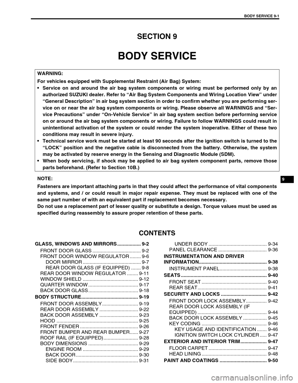
CONTENTS
GLASS, WINDOWS AND MIRRORS ................. 9-2
FRONT DOOR GLASS ................................... 9-2
FRONT DOOR WINDOW REGULATOR ........ 9-6
DOOR MIRROR .......................................... 9-7
REAR DOOR GLASS (IF EQUIPPED) ....... 9-8
REAR DOOR WINDOW REGULATOR ........ 9-11
WINDOW SHIELD ........................................ 9-12
QUARTER WINDOW .................................... 9-17
BACK DOOR GLASS .................................... 9-18
BODY STRUCTURE......................................... 9-19
FRONT DOOR ASSEMBLY .......................... 9-19
REAR DOOR ASSEMBLY ............................ 9-22
BACK DOOR ASSEMBLY ............................ 9-23
HOOD ........................................................... 9-25
FRONT FENDER .......................................... 9-26
FRONT BUMPER AND REAR BUMPER...... 9-27
ROOF RAIL (IF EQUIPPED) ......................... 9-28
BODY DIMENSIONS .................................... 9-29
ENGINE ROOM ........................................ 9-29
BACK DOOR ............................................. 9-30
SIDE BODY ............................................... 9-31UNDER BODY .......................................... 9-34
PANEL CLEARANCE ................................... 9-36
INSTRUMENTATION AND DRIVER
INFORMATION................................................. 9-38
INSTRUMENT PANEL .................................. 9-38
SEATS .............................................................. 9-40
FRONT SEAT ............................................... 9-40
REAR SEAT.................................................. 9-41
SECURITY AND LOCKS ................................. 9-42
FRONT DOOR LOCK ASSEMBLY............... 9-42
REAR DOOR LOCK ASSEMBLY (IF
EQUIPPED) .................................................. 9-44
BACK DOOR LOCK ASSEMBLY ................. 9-45
KEY CODING ............................................... 9-46
KEY USAGE AND IDENTIFICATION ....... 9-46
IGNITION SWITCH LOCK CYLINDER ..... 9-47
EXTERIOR AND INTERIOR TRIM ................... 9-47
FLOOR CARPET .......................................... 9-47
HEAD LINING ............................................... 9-48
PAINT AND COATINGS .................................. 9-50 WARNING:
For vehicles equipped with Supplemental Restraint (Air Bag) System:
Service on and around the air bag system components or wiring must be performed only by an
authorized SUZUKI dealer. Refer to “Air Bag System Components and Wiring Location View” under
“General Description” in air bag system section in order to confirm whether you are performing ser-
vice on or near the air bag system components or wiring. Please observe all WARNINGS and “Ser-
vice Precautions” under “On-Vehicle Service” in air bag system section before performing service
on or around the air bag system components or wiring. Failure to follow WARNINGS could result in
unintentional activation of the system or could render the system inoperative. Either of these two
conditions may result in severe injury.
Technical service work must be started at least 90 seconds after the ignition switch is turned to the
“LOCK” position and the negative cable is disconnected from the battery. Otherwise, the system
may be activated by reserve energy in the Sensing and Diagnostic Module (SDM).
When body servicing, if shock may be applied to air bag system component parts, remove those
parts beforehand. (Refer to Section 10B.)
NOTE:
Fasteners are important attaching parts in that they could affect the performance of vital components
and systems, and / or could result in major repair expense. They must be replaced with one of the
same part number of with an equivalent part if replacement becomes necessary.
Do not use a replacement part of lesser quality or substitute a design. Torque values must be used as
specified during reassembly to assure proper retention of these parts.