Page 317 of 447

BODY SERVICE 9-13
REMOVAL
1) Clean both inside and outside of glass and around it.
2) Remove wiper arms and garnish.
3) Using tape, cover body surface around glass to prevent any
damage.
4) Remove rear view mirror, sunvisor, and front pillar trims (right
& left).
5) If necessary, remove instrument panel. Refer to “INSTRU-
MENT PANEL” in this section.
6) If necessary, remove head lining. Refer to “HEAD LINING” in
this section.
7) Remove (or cut) windshield molding.
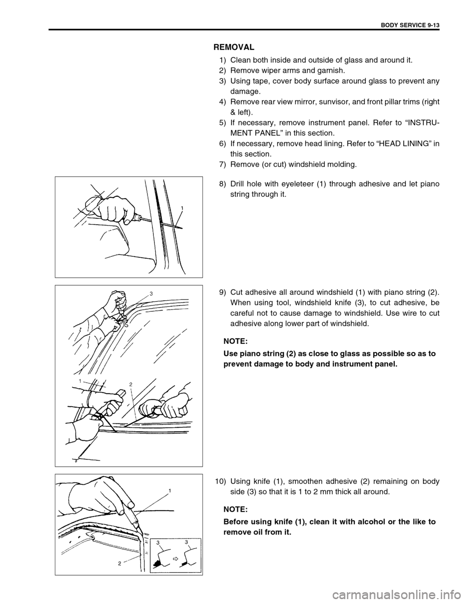
8) Drill hole with eyeleteer (1) through adhesive and let piano
string through it.
9) Cut adhesive all around windshield (1) with piano string (2).
When using tool, windshield knife (3), to cut adhesive, be
careful not to cause damage to windshield. Use wire to cut
adhesive along lower part of windshield.
10) Using knife (1), smoothen adhesive (2) remaining on body
side (3) so that it is 1 to 2 mm thick all around.
NOTE:
Use piano string (2) as close to glass as possible so as to
prevent damage to body and instrument panel.
NOTE:
Before using knife (1), clean it with alcohol or the like to
remove oil from it.
Page 342 of 447
9-38 BODY SERVICE
INSTRUMENTATION AND DRIVER INFORMATION
INSTRUMENT PANEL
REMOVAL
1) Disconnect negative cable at battery.
2) Disable air bag system, if equipped. Refer to “DISABLE AIR
BAG SYSTEM” in Section 10B.
3) Remove steering column hole cover (1).
4) Remove glove box (1) and food latch release lever (2).
5) Disconnect instrument panel harness connectors, antenna
and heater control cables which need to be disconnected for
removal for instrument panel.
6) Remove instrument panel ground wire.
7) Remove steering column assembly referring to “STEERING
COLUMN ASSEMBLY” in Section 3C.
8) Remove front pillar trims (1) and dash side trims (2).
9) Remove speaker covers (3).WARNING:
See WARNING at the beginning of this section.
“A”
“A”“A”
“A”
“A”
1
2“A” 1
3
“A”
Page 351 of 447
BODY SERVICE 9-47
IGNITION SWITCH LOCK CYLINDER
REMOVAL AND INSTALLATION
Refer to “STEERING LOCK ASSEMBLY (IGNITION SWITCH)” in
Section 3C.
ELECTRICAL DIAGNOSIS
For ignition switch electrical troubleshooting, refer to “IGNITION
SWITCH” in Section 8.
EXTERIOR AND INTERIOR TRIM
FLOOR CARPET
REMOVAL
1) Remove front seats and rear seat cushion.
2) Remove seat belt lower anchor bolt.
3) Remove dash side trims, front side sill scuffs, center pillar inner lower trims, quarter inner trims and rear side
sill scuffs.
4) Remove parking brake lever cover and console box.
5) Remove floor carpet.
INSTALLATION
Reverse removal sequence to install front floor carpet, noting the following instruction.
For tightening torque of seat belt anchor bolt, refer to “FRONT SEAT BELT” in Section 10.
1. Floor carpet
2. Dash panel silencer
3. Silencer seat
Page 352 of 447
9-48 BODY SERVICE
HEAD LINING
REMOVAL
1) Remove interior light (1).
2) Remove head lining clip (2).
3) Remove sun visor (3).
4) Remove luggage room light (1).
5) Remove head lining clip (2).
6) Remove assistant grip (1).
7) Remove door opening trim (2) and remove inner trims cover-
ing headlining (3).
8) Remove head lining clips (4) and remove head lining.
NOTE:
Adhesive is used to attach head lining.
Clear adhesive from headlining and roof after removing
head lining if applied.
[A] : For 3-door model
[B] : For 5-door model
1
11
4
4
1
2
2
3
3 3 2
33
[A]
[B]