2000 SUZUKI SWIFT low oil pressure
[x] Cancel search: low oil pressurePage 52 of 447

7B-10 AUTOMATIC TRANSMISSION (4 A/T)
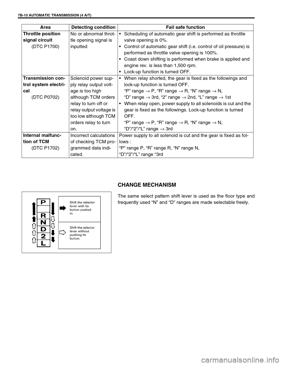
CHANGE MECHANISM
The same select pattern shift lever is used as the floor type and
frequently used “N” and “D” ranges are made selectable freely. Throttle position
signal circuit
(DTC P1700)No or abnormal throt-
tle opening signal is
inputtedScheduling of automatic gear shift is performed as throttle
valve opening is 0%.
Control of automatic gear shift (i.e. control of oil pressure) is
performed as throttle valve opening is 100%.
Coast down shifting is performed when brake is applied and
engine rev. is less than 1,500 rpm.
Lock-up function is turned OFF.
Transmission con-
trol system electri-
cal
(DTC P0702)Solenoid power sup-
ply relay output volt-
age is too high
although TCM orders
relay to turn off or
relay output voltage is
too low although TCM
orders relay to turn
on.When relay shorted, the gear is fixed as the followings and
lock-up function is turned OFF.
“P” range →
P, “R” range →
R, “N” range →
N,
“D” range →
3rd, “2” range →
2nd, “L” range →
1st
When relay open, power supply to all solenoids is cut and the
gear is fixed as the followings. Lock-up function is turned
OFF.
“P” range →
P, “R” range →
R, “N” range →
N,
“D”/“2”/“L” range →
3rd
Internal malfunc-
tion of TCM
(DTC P1702)Incorrect calculations
of checking TCM pro-
grammed data indi-
cated.Power supply to all solenoid is cut and the gear is fixed as fol-
lows :
“P” range P, “R” range R, “N” range N,
“D”/“2”/“L” range “3rd Area Detecting condition Fail safe function
Page 64 of 447

7B-22 AUTOMATIC TRANSMISSION (4 A/T)
LINE PRESSURE TEST
Purpose of this test is to check operating conditions of each part
by measuring fluid pressure in fluid pressure line.
Line pressure test requires following conditions.
Automatic fluid is at normal operating temperature (70 –
80°C /158 – 176°F).
Fluid is filled to proper level (between FULL and LOW on
dipstick).
1) Apply parking brake securely and place chocks against
wheels.
2) Remove fluid pressure check hole plug bolt.
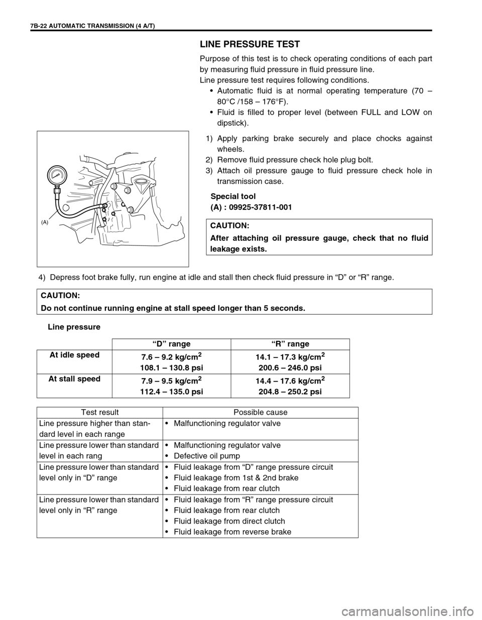
3) Attach oil pressure gauge to fluid pressure check hole in
transmission case.
Special tool
(A) : 09925-37811-001
4) Depress foot brake fully, run engine at idle and stall then check fluid pressure in “D” or “R” range.
Line pressureCAUTION:
After attaching oil pressure gauge, check that no fluid
leakage exists.
(A)
CAUTION:
Do not continue running engine at stall speed longer than 5 seconds.
“D” range “R” range
At idle speed
7.6 – 9.2 kg/cm
2
108.1 – 130.8 psi14.1 – 17.3 kg/cm
2
200.6 – 246.0 psi
At stall speed
7.9 – 9.5 kg/cm
2
112.4 – 135.0 psi14.4 – 17.6 kg/cm
2
204.8 – 250.2 psi
Test result Possible cause
Line pressure higher than stan-
dard level in each rangeMalfunctioning regulator valve
Line pressure lower than standard
level in each rangMalfunctioning regulator valve
Defective oil pump
Line pressure lower than standard
level only in “D” rangeFluid leakage from “D” range pressure circuit
Fluid leakage from 1st & 2nd brake
Fluid leakage from rear clutch
Line pressure lower than standard
level only in “R” rangeFluid leakage from “R” range pressure circuit
Fluid leakage from rear clutch
Fluid leakage from direct clutch
Fluid leakage from reverse brake
Page 184 of 447

7C-2 CLUTCH
GENERAL DESCRIPTION
The clutch is a diaphragm-spring clutch of a dry single disc type. The diaphragm spring is of a tapering-finger
type, which is a solid ring in the outer diameter part, with a series of tapered fingers pointing inward.
The disc, carrying four torsional coil springs, is positioned on the transmission input shaft with an involute spline
fit.
The clutch cover is secured to the flywheel, and carries the diaphragm spring in such a way that the peripheral
edge part of the spring pushes on the pressure plate against the flywheel (with the disc in between), when the
clutch release bearing is held back. This is the engaged condition of the clutch.
Depressing the clutch pedal causes the release bearing to advance and pushes on the tips of the tapered fin-
gers of the diaphragm spring. When this happens, the diaphragm spring pulls the pressure plate away from the
flywheel, thereby interrupting the flow of drive from flywheel through clutch disc to transmission input shaft.
1. Crankshaft 6. Diaphragm spring
2. Flywheel 7. Release bearing
3. Clutch disc 8. Input shaft bearing
4. Pressure plate 9. Input shaft
5. Clutch cover 10. Release shaft
Page 245 of 447

BODY ELECTRICAL SYSTEM 8-1
6F1
6F2
6G
6H
6K
7A
7A1
7B1
7C1
7D
7E
7F
8A
8
8D
8E
9
10
10A
10B
SECTION 8
BODY ELECTRICAL SYSTEM
CONTENTS
DIAGNOSIS ........................................................ 8-3
HEADLIGHT .................................................... 8-3
HEADLIGHTS WITH LEVELING SYSTEM
(IF EQUIPPED) ............................................... 8-3
TURN SIGNAL AND HAZARD WARNING
LIGHT .............................................................. 8-3
CLEARANCE, TAIL AND LICENSE
PLATE LIGHT ................................................. 8-4
BACK-UP LIGHT ............................................. 8-4
BRAKE LIGHT ................................................ 8-4
FRONT FOG LIGHT (IF EQUIPPED) ............. 8-4
REAR FOG LIGHT (IF EQUIPPED) ................ 8-4
SPEEDOMETER AND VSS ............................ 8-5
FUEL METER AND FUEL LEVEL SENSOR
(GAUGE UNIT) ............................................... 8-5
ENGINE COOLANT TEMPERATURE (ECT)
METER AND ECT SENSOR ........................... 8-5
OIL PRESSURE WARNING LIGHT ................ 8-5
BRAKE AND PARKING BRAKE WARNING
LIGHT .............................................................. 8-6
REAR WINDOW DEFOGGER ........................ 8-6
WIPERS AND WASHERS .............................. 8-6
FRONT WIPER AND WASHER .................. 8-6
REAR WIPER AND WASHER (IF
EQUIPPED)................................................. 8-6
POWER WINDOW CONTROL SYSTEM
(IF EQUIPPED) ............................................... 8-7
CIGARETTE LIGHTER ................................... 8-7
POWER DOOR LOCK CONTROL SYSTEM
(IF EQUIPPED) ............................................... 8-7
KEYLESS ENTRY SYSTEM (IF
EQUIPPED) .................................................... 8-7POWER DOOR MIRROR CONTROL
SYSTEM (IF EQUIPPED) ............................... 8-8
INTERIOR LIGHT ........................................... 8-8
HORN ............................................................. 8-8
IGNITION KEY REMAINDER (IF EQUIPPED)
AND LIGHT REMAINDER WARNING
BUZZER.......................................................... 8-8
SEAT BELT WARNING LIGHT (IF
EQUIPPED) .................................................... 8-8
FRONT SEAT HEATER (IF EQUIPPED) ....... 8-9
ON-VEHICLE SERVICE ..................................... 8-9
CAUTIONS IN SERVICING ............................ 8-9
HEADLIGHT ................................................... 8-9
HEADLIGHT SWITCH ................................ 8-9
HEADLIGHT ASSEMBLY ......................... 8-10
HEADLIGHT BULB ................................... 8-10
HEADLIGHT AIMING ADJUSTMENT
WITH SCREEN ......................................... 8-11
HEADLIGHT LEVELING SWITCH (IF
EQUIPPED) .............................................. 8-12
TURN SIGNAL AND HAZARD WARNING
LIGHTS ......................................................... 8-12
TURN SIGNAL LIGHT SWITCH ............... 8-12
REMOVAL AND INSTALLATION ............. 8-12
TURN SIGNAL AND HAZARD RELAY ..... 8-13
HAZARD SWITCH .................................... 8-13
FRONT FOG LIGHTS (IF EQUIPPED)......... 8-13
FRONT FOG LIGHT SWITCH .................. 8-13
REAR FOG LIGHT (IF EQUIPPED) ............. 8-14
REAR FOG LIGHT SWITCH..................... 8-14
IGNITION SWITCH ....................................... 8-14
COMBINATION METER ............................... 8-15 WARNING:
For vehicles equipped with Supplemental Restraint (Air Bag) System :
Service on and around the air bag system components or wiring must be performed only by an
authorized SUZUKI dealer. Refer to “Air Bag System Components and Wiring Location View” under
“General Description” in air bag system section in order to confirm whether you are performing ser-
vice on or near the air bag system components or wiring. Please observe all WARNINGS and “Ser-
vice Precautions” under “On-Vehicle Service” in air bag system section before performing service
on or around the air bag system components or wiring. Failure to follow WARNINGS could result in
unintentional activation of the system or could render the system inoperative. Either of these two
conditions may result in severe injury.
Technical service work must be started at least 90 seconds after the ignition switch is turned to the
“LOCK” position and the negative cable is disconnected from the battery. Otherwise, the system
may be activated by reserve energy in the Sensing and Diagnostic Module (SDM).
Page 249 of 447

BODY ELECTRICAL SYSTEM 8-5
SPEEDOMETER AND VSS
FUEL METER AND FUEL LEVEL SENSOR (GAUGE UNIT)
ENGINE COOLANT TEMPERATURE (ECT) METER AND ECT SENSOR
OIL PRESSURE WARNING LIGHT
Condition Possible Cause Correction
Speedometer shows
no operation or incor-
rect operation“IG/METER” and/or “RADIO/DOME” fuse(s)
blownReplace fuse(s) to check for short.
VSS faulty Check VSS.
Printed plate in combination meter faulty Check printed plate.
Wiring or grounding faulty Repair circuit.
Signal rotor on differential case faulty Check signal rotor.
Speedometer faulty Replace speedometer.
Condition Possible Cause Correction
Fuel meter shows no
operation or incorrect
operation“IG/METER” fuse blown Replace fuse to check for short.
Fuel gauge unit faulty Check fuel gauge unit.
Printed plate in combination meter faulty Check printed plate.
Fuel meter faulty Check fuel meter.
Wiring or grounding faulty Repair circuit.
Condition Possible Cause Correction
Engine coolant temp.
meter shows no oper-
ation or incorrect
operation“IG/METER” fuse blown Replace fuse to check for short.
ECT meter faulty Check ECT meter.
Printed plate in combination meter faulty Check printed plate.
ECT sensor faulty Check ECT sensor.
Wiring or grounding faulty Repair circuit.
Condition Possible Cause Correction
Oil pressure warning
light does not light up
when turn the ignition
switch to ON position
at engine offBulb in combination meter blown Replace bulb.
“IG/METER” fuse blown Replace fuse to check for short.
Printed plate in combination meter faulty Check printed plate.
Oil pressure switch faulty Check oil pressure switch.
Wiring or grounding faulty Repair circuit.
Oil pressure warning
light stay onOil pressure switch faulty Check oil pressure switch.
Page 263 of 447

BODY ELECTRICAL SYSTEM 8-19
PARKING BRAKE SWITCH
INSPECTION
Check for continuity between parking brake switch terminal and
body ground as shown in figure.
If found defective, replace switch.
Parking brake switch specification
OFF position (parking brake released) (1) :
No continuity
ON position (parking brake lever pulled up) (2) :
Continuity
REAR WINDOW DEFOGGER
DEFOGGER SWITCH
INSPECTION
Check for continuity between terminals at each switch position as
shown below. If check result is not satisfied, replace.
DEFOGGER WIRE
INSPECTION
SwitchPositionTerminal
ON (PUSH IN)IG LOAD E IL ILE
OFF
NOTE:
When cleaning rear window glass, use a dry cloth to
wipe it along heat wire (1) direction.
When cleaning glass, do not use detergent or abra-
sive-containing glass cleaner.
When measuring wire voltage, use a tester with nega-
tive probe (2) wrapped with a tin foil (3) which should
be held down on wire by finger pressure.