2000 SUZUKI SWIFT wheel
[x] Cancel search: wheelPage 228 of 447

7F-6 REAR DIFFERENTIAL
DIFFERENTIAL UNIT
DISMOUNTING
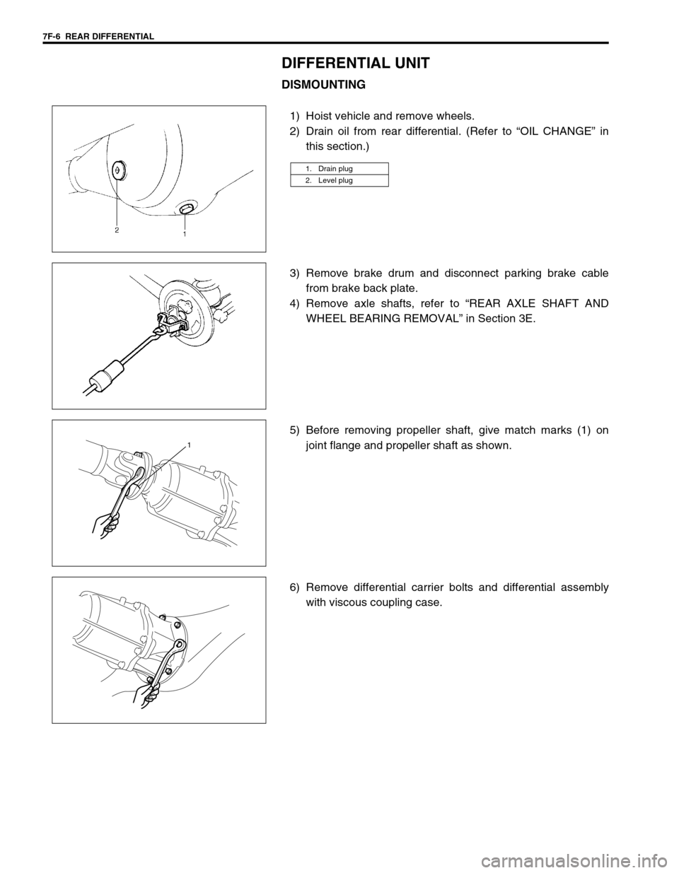
1) Hoist vehicle and remove wheels.
2) Drain oil from rear differential. (Refer to “OIL CHANGE” in
this section.)
3) Remove brake drum and disconnect parking brake cable
from brake back plate.
4) Remove axle shafts, refer to “REAR AXLE SHAFT AND
WHEEL BEARING REMOVAL” in Section 3E.
5) Before removing propeller shaft, give match marks (1) on
joint flange and propeller shaft as shown.
6) Remove differential carrier bolts and differential assembly
with viscous coupling case.
1. Drain plug
2. Level plug
1
Page 229 of 447

REAR DIFFERENTIAL 7F-7
REMOUNTING
Reverse removal procedure for installation, noting the following.
Rear Differential
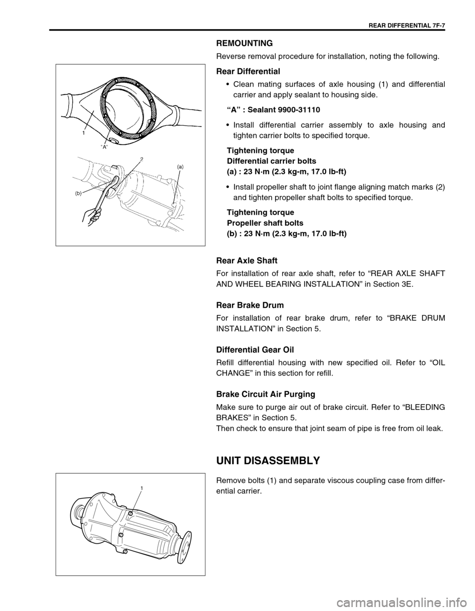
Clean mating surfaces of axle housing (1) and differential
carrier and apply sealant to housing side.
“A” : Sealant 9900-31110
Install differential carrier assembly to axle housing and
tighten carrier bolts to specified torque.
Tightening torque
Differential carrier bolts
(a) : 23 N·m (2.3 kg-m, 17.0 lb-ft)
Install propeller shaft to joint flange aligning match marks (2)
and tighten propeller shaft bolts to specified torque.
Tightening torque
Propeller shaft bolts
(b) : 23 N·m (2.3 kg-m, 17.0 lb-ft)
Rear Axle Shaft
For installation of rear axle shaft, refer to “REAR AXLE SHAFT
AND WHEEL BEARING INSTALLATION” in Section 3E.
Rear Brake Drum
For installation of rear brake drum, refer to “BRAKE DRUM
INSTALLATION” in Section 5.
Differential Gear Oil
Refill differential housing with new specified oil. Refer to “OIL
CHANGE” in this section for refill.
Brake Circuit Air Purging
Make sure to purge air out of brake circuit. Refer to “BLEEDING
BRAKES” in Section 5.
Then check to ensure that joint seam of pipe is free from oil leak.
UNIT DISASSEMBLY
Remove bolts (1) and separate viscous coupling case from differ-
ential carrier.1
Page 354 of 447

9-50 BODY SERVICE
PAINT AND COATINGS
ANTI-CORROSION TREATMENT
As rust proof treatment, steel sheets are given corrosion resistance on the interior and/or exterior.
These corrosion resistance steel sheet materials are called one of two-side galvanized steel sheets.
It is for the sake of rust protection that these materials are selected and given a variety of treatments as
described blow.
Steel sheets are treated with cathodic electroprimer which is excellent in corrosion resistance.
Rust proof wax coatings are applied to door and side sill insides where moisture is liable to stay.
Vinyl coating is applied to body underside and wheel housing inside.
Sealer is applied to door hem, engine compartment steel sheet-to-steel sheet joint, and the like portions to
prevent water penetration and resulting in rust occurrence.
In panel replacement or collision damage repair, leaving the relevant area untreated as it is in any operation
which does disturb the above-mentioned rust proof treatment will cause corrosion to that area. Therefore, it is
the essential function of any repair operation to correctly recoat the related surfaces of the relevant area.
All the metal panels are coated with metal conditioners and primer coating during vehicle production. Following
the repair and/or replacement parts installation, every accessible bare metal surface should be cleaned and
coated with rust proof primer. Perform this operation prior to the application of sealer and rust proof wax coating.
Sealer is applied to the specific joints of a vehicle during production. The sealer is intended to prevent dust from
entering the vehicle and serves also as an anticorrosion barrier. The sealer is applied to the door and hood hem
areas and between panels. Correct and reseal the originally sealed joints if damaged. Reseal the attaching
joints of a new replacement panel and reseal the hem area of a replacement door or hood.
Use a quality sealer to seal the flanged joints, overlap joints and seams. The sealer must have flexible character-
istics and paint ability after it’s applied to repair areas.
For the sealer to fill open joints, use caulking material. Select a sealer in conformance with the place and pur-
pose of a specific use. Observe the manufacturer’s label-stand instructions when using the sealer.
In many cases, repaired places require color painting. When this is required, follow the ordinary techniques
specified for the finish preparation, color painting and undercoating build-up.
Rust proof wax, a penetrative compound, is applied to the metal-to-metal surfaces (door and side sill insides)
where it is difficult to use ordinary undercoating material for coating. Therefore, when selecting the rust proof
wax, it may be the penetrative type.
During the undercoating (vinyl coating) application, care should be taken that sealer is not applied to the engine-
related parts and shock absorber mounting or rotating parts. Following the under coating, make sure that body
drain holes are kept open.
The sequence of the application steps of the anti-corrosion materials are as follows:
1) Clean and prepare the metal surface.
2) Apply primer.
3) Apply sealer (all joints sealed originally).
4) Apply color in areas where color is required such as hem flanges, exposed joints and under body compo-
nents.
5) Apply anticorrosion compound (penetrative wax).
6) Apply undercoating (rust proof material).WARNING:
Standard shop practices, particularly eye protection, should be followed during the performance of the
below-itemized operations to avoid personal injury.
Page 381 of 447

AIR BAG SYSTEM 10B-7
The adapter will also give an idea of whether contact tension is
sufficient, helping to find an open or intermittent open due to poor
terminal contact.
Special tool
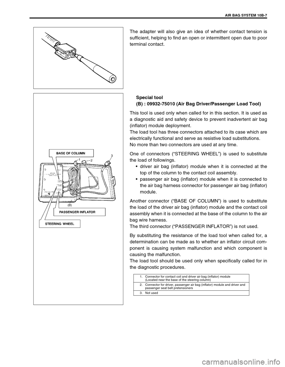
(B) : 09932-75010 (Air Bag Driver/Passenger Load Tool)
This tool is used only when called for in this section. It is used as
a diagnostic aid and safety device to prevent inadvertent air bag
(inflator) module deployment.
The load tool has three connectors attached to its case which are
electrically functional and serve as resistive load substitutions.
No more than two connectors are used at any time.
One of connectors (“STEERING WHEEL”) is used to substitute
the load of followings.
driver air bag (inflator) module when it is connected at the
top of the column to the contact coil assembly.
passenger air bag (inflator) module when it is connected to
the air bag harness connector for passenger air bag (inflator)
module.
Another connector (“BASE OF COLUMN”) is used to substitute
the load of the driver air bag (inflator) module and the contact coil
assembly when it is connected at the base of the column to the air
bag wire harness.
The third connector (“PASSENGER INFLATOR”) is not used.
By substituting the resistance of the load tool when called for, a
determination can be made as to whether an inflator circuit com-
ponent is causing system malfunction and which component is
causing the malfunction.
The load tool should be used only when specifically called for in
the diagnostic procedures.
1. Connector for contact coil and driver air bag (inflator) module
(Located near the base of the steering column)
2. Connector for driver, passenger air bag (inflator) module and driver and
passenger seat belt pretensioners
3. Not used
Page 404 of 447

10B-30 AIR BAG SYSTEM
DIAGNOSTIC FLOW TABLE
DTC B1021 :
Fig. for STEP 1 and 2
Fig. for STEP 2Step Action Yes No
1 1) With ignition switch OFF, disconnect contact coil con-
nector located near the base of the steering column.
2) Check proper connection to contact coil at terminals
in “Q01” connector.
3) If OK then connect Special Tool (B) to contact coil
connector disconnected at step 1).
With ignition switch ON, is DTC B1021 current?Go to step 2. Go to step 3.
2 1) With ignition switch OFF, disconnect SDM.
2) Check proper connection to SDM at terminals “Q06-9”
and “Q06-10”.
3) If OK then measure resistance between “Q06-9” and
“Q06-10” terminals with connected Special Tool (B).
Is resistance 4.5 Ω or less?Substitute a known-
good SDM and
recheck.Repair high resis-
tance or open in
“GRN” or “GRN/RED”
wire circuit.
3 1) With ignition switch OFF, disconnect Special Tool (B)
then reconnect contact coil connector located near
the base of the steering column.
2) Remove driver air bag (inflator) module from steering
wheel (Refer to DRIVER AIR BAG (INFLATOR)
MODULE in Section 3C).
3) Check proper connection to driver air bag (inflator)
module at terminals in “Q08” connector.
4) If OK then connect Special Tool (B) to “Q08” connec-
tor.
With ignition switch ON, is DTC B1021 current?Ignition switch OFF.
Replace contact coil
assembly (Refer to
COMBINATION
SWITCH/CON-
TACT COIL AND
COMBINATION
SWITCH ASSEM-
BLY in Section 3C).Ignition switch OFF.
Replace driver air
bag (inflator) module
(Refer to DRIVER
AIR BAG (INFLA-
TOR) MODULE in
Section 3C).
BASE OF
COLUMN
“Q01”
Page 405 of 447

AIR BAG SYSTEM 10B-31
Fig. for STEP 3
Special tool
(A) : 09932-76010
(B) : 09932-75010
DTC B1022 :
NOTE:
Upon completion of inspection and repair work, perform following items.
Reconnect all air bag system components, ensure all components are properly mounted.
Clear diagnostic trouble codes (Refer to DTC CLEARANCE), if any.
Repeat AIR BAG DIAGNOSTIC SYSTEM CHECK to confirm that the trouble has been corrected.
Step Action Yes No
1 1) With ignition switch OFF, disconnect con-
tact coil connector located near the base of
the steering column.
2) Check proper connection to contact coil at
terminals in “Q01” connector.
3) If OK then connect Special Tool (B) to con-
tact coil connector disconnected at step 1).
With ignition switch ON, is DTC B1022 current?Go to step 2. Go to step 3.
2 1) With ignition switch OFF, disconnect SDM.
2) Check proper connection to SDM at termi-
nals “Q06-9” and “Q06-10”.
3) If OK then measure resistance between
“Q06-9” and “Q06-10” terminals with con-
nected Special Tool (B).
Is resistance 1.7 Ω or more?Substitute a known-good
SDM and recheck.Repair short from “GRN”
wire circuit to “GRN/RED”
wire circuit or from “GRN”
or “GRN/RED” wire cir-
cuit to other wire circuit.
3 1) With ignition switch OFF, disconnect Spe-
cial Tool (B) then reconnect contact coil
connector located near the base of the
steering column.
2) Remove driver air bag (inflator) module
from steering wheel (Refer to DRIVER AIR
BAG (INFLATOR) MODULE in Section 3C).
3) Check proper connection to driver air bag
(inflator) module at terminals in “Q08” con-
nector.
4) If OK then connect Special Tool (B) to “Q08”
connector.
With ignition switch ON, is DTC B1022 current?Ignition switch OFF.
Replace contact coil
assembly (Refer to COM-
BINATION SWITCH/
CONTACT COIL AND
COMBINATION SWITCH
ASSEMBLY in Section
3C).Ignition switch OFF.
Replace driver air bag
(inflator) module (Refer to
DRIVER AIR BAG
(INFLATOR) MODULE in
Section 3C).
Page 407 of 447

AIR BAG SYSTEM 10B-33
DTC B1024 :
Fig. for STEP 1 and 2
Fig. for STEP 2Step Action Yes No
1 1) With ignition switch OFF, disconnect contact coil
connector located near the base of the steering col-
umn.
2) Check proper connection to contact coil at terminals
in “Q01” connector.
3) If OK then connect Special Tool (B) to contact coil
connector disconnected at step 1).
With ignition switch ON, is DTC B1024 current?Go to step 2. Go to step 3.
2 1) With ignition switch OFF, disconnect Special Tool
(B) and SDM.
2) Measure resistance between “Q06-9” terminal and
body ground and between “Q06-10” terminal and
body ground.
Are they 10 Ω or more?Substitute a known-
good SDM and
recheck.Repair short from
“GRN” or “GRN/RED”
wire circuit to ground.
3 1) With ignition switch OFF, disconnect Special Tool
(B) then reconnect contact coil connector located
near the base of the steering column.
2) Remove driver air bag (inflator) module from steer-
ing wheel (Refer to DRIVER AIR BAG (INFLATOR)
MODULE in Section 3C).
3) Check proper connection to driver air bag (inflator)
module at terminals in “Q08” connector.
4) If OK then connect Special Tool (B) to “Q08” con-
nector.
With ignition switch ON, is DTC B1024 current?Ignition switch OFF.
Replace contact coil
assembly (Refer to
COMBINATION
SWITCH/CONTACT
COIL AND COMBI-
NATION SWITCH
ASSEMBLY in Sec-
tion 3C).Ignition switch OFF.
Replace driver air bag
(inflator) module
(Refer to DRIVER AIR
BAG (INFLATOR)
MODULE in Section
3C).
BASE OF
COLUMN
“Q01”
Page 408 of 447

10B-34 AIR BAG SYSTEM
Fig. for STEP 3
Special tool
(A) : 09932-76010
(B) : 09932-75010
DTC B1025 :
NOTE:
Upon completion of inspection and repair work, perform following items.
Reconnect all air bag system components, ensure all components are properly mounted.
Clear diagnostic trouble codes (Refer to DTC CLEARANCE), if any.
Repeat AIR BAG DIAGNOSTIC SYSTEM CHECK to confirm that the trouble has been corrected.
Step Action Yes No
1 1) With ignition switch OFF, disconnect con-
tact coil connector located near the base of
the steering column.
2) Check proper connection to contact coil at
terminals in “Q01” connector.
3) If OK then connect Special Tool (B) to con-
tact coil connector disconnected at step 1).
With ignition switch ON, is DTC B1025 current?Go to step 2. Go to step 3.
2 1) With ignition switch OFF, disconnect Spe-
cial Tool (B) and SDM.
2) Measure voltage from “ Q06-9” terminal to
body ground and from “Q06-10” terminal to
body ground.
With ignition switch ON, are they 1 V or less?Substitute a known-good
SDM and recheck.Repair short from “GRN”
or “GRN/RED” wire cir-
cuit to power circuit.
3 1) With ignition switch OFF, disconnect Spe-
cial Tool (B) then reconnect contact coil
connector located near the base of the
steering column.
2) Remove driver air bag (inflator) module
from steering wheel (Refer to DRIVER AIR
BAG (INFLATOR) MODULE in Section 3C).
3) Check proper connection to driver air bag
(inflator) module at terminals in “Q08” con-
nector.
4) If OK then connect Special Tool (B) to “Q08”
connector.
With ignition switch ON, is DTC B1025 current?Ignition switch OFF.
Replace contact coil
assembly (Refer to COM-
BINATION SWITCH/
CONTACT COIL AND
COMBINATION SWITCH
ASSEMBLY in Section
3C).Ignition switch OFF.
Replace driver air bag
(inflator) module (Refer to
DRIVER AIR BAG
(INFLATOR) MODULE in
Section 3C).